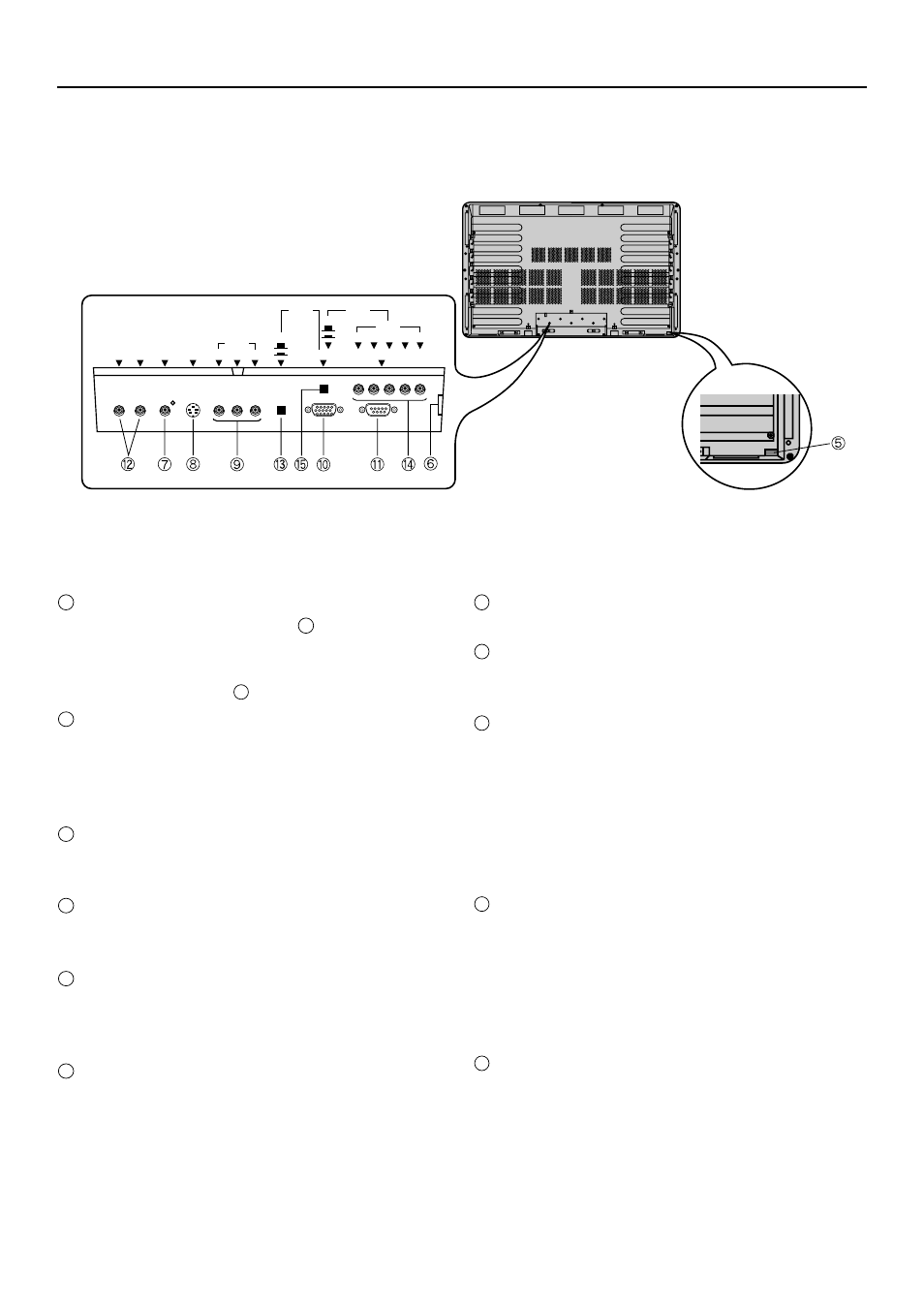
Names of parts and their functions, Rear view – FUJITSU PDS4207W-H User Manual
Page 12
12
5
Power switch
• When pressed, power lamp
1
lights red, and the
power can be turned on or off by the remote control-
ler. When this switch is pressed again, the power is
cut and power lamp
1
goes off.
6
Power input terminal
• Firmly insert the accessory power cord as far as it will
go into the power input terminal.
• Firmly push the power cord plug as far as it will go
into the power socket. (100–240 VAC)
7
Video input terminal (VIDEO INPUT)
• Connects to the video output terminal of a video deck
or video disc player.
8
S video input terminal (S-VIDEO INPUT)
• Connects to the S video output terminal of a video
deck or video disc player.
9
Component video input terminal (COMPONENT
VIDEO INPUT)
• Connects to the component video output terminal of
DVD and similar devices.
10
RGB 1 input terminal (RGB 1 INPUT)
• Connects to the computer monitor's (analog RGB)
output terminal.
Signals up to SVGA can be displayed.
Cables connecting the personal computer vary ac-
cording to the type of machine, so consult your prod-
uct dealer.
11
RS-232C input terminal (RS-232C)
• Connects to the computer RS-232C output terminal.
12
Audio input terminals (AUDIO INPUT)
• Connects to the audio output terminal of a video deck
or similar device.
13
RGB 1 Sync switch (RGB 1 SYNC SW TTL/ANALOG
(75
Ω
))
• For switching the RGB 1 terminals' 13-pin horizontal
sync and 14-pin vertical sync to terminate with 75
Ω
.
When an analog synchronous signal is input at the
RGB 1 terminal, be sure that this switch is set to ANA-
LOG (75
Ω
). For connection to a personal computer,
be sure it is set to TTL.
14
RGB 2 input terminal (RGB 2 INPUT)
• Connects to the computer monitor's (analog RGB)
output terminal.
Signals from VGA to XGA can be displayed.
Cables connecting the personal computer vary ac-
cording to the type of machine, so consult your prod-
uct dealer.
15
RGB 2 Sync switch (RGB 2 SYNC SW TTL/ANALOG
(75
Ω
))
• For switching the RGB 2 terminals' H terminal hori-
zontal sync and V terminal vertical sync to terminate
with 75
Ω
.
When an analog synchronous signal is input at the
RGB 2 terminal, be sure that this switch is set to ANA-
LOG (75
Ω
). For connection to a personal computer,
be sure it is set to TTL.
AUDIO
INPUT
SYNC SW
SYNC SW
TTL
ANALOG
(75
Ω
)
TTL
ANALOG
(75
Ω
)
VIDEO
INPUT
S-VIDEO
INPUT
R
R
G
B
H
V
INPUT
RS232C
Y Pb/B-Y Pr/R-Y
L
CONPONENT-VIDEO
INPUT
RGB 1
RGB 2
INPUT
NAMES OF PARTS AND THEIR FUNCTIONS
Rear view