Installation, Installing dispenser in counter – Follett 00119628R01 User Manual
Page 7
Installation
Installing dispenser in counter
Note:
All dispensers must be supported from below with supplied 4" – 6" (102 – 153mm) adjustable leg accessory,
or equivalent. Do not hang dispenser on flange.
All dispensers must be installed level in both directions to ensure proper operation.
1.
Check that dispenser location meets all requirements in this manual and cut counter as shown.
2.
Place support blocks in cabinet to raise dispenser to a height of 12" (305mm).
3.
Place dispenser in counter onto support blocks.
4.
Attach adjustable legs to dispenser.
5.
Remove support blocks and lower dispenser feet to floor.
6.
Adjust legs for 1/8" (4mm) clearance between dispenser lip and countertop to verify there is no load on flange.
7.
Apply a bead approximately 1/4" (6mm) in diameter of NSF-listed silicone sealant (Dow Corning RTV-732 or
equivalent) around perimeter of dispenser where it meets counter. Smooth sealant to a 1/8" (4mm) radius.
8.
Install a PVC drain line with at least a 1/4" per foot (20mm per 1m) slope. Insulate drain line to prevent
condensation.
Note:
Do not apply excessive heat if any sweating of fittings is necessary. Heat conduction through metal may
melt threads in plastic drain.
Do not reduce drain line size or tie drains together.
9.
Install carbonator pump. See instruction enclosed with pump for detailed installation instructions.
10. Make electrical connections in accordance with applicable wiring diagrams provided. Provide disconnects within
10 ft (3m) of dispenser and icemaker for servicing.
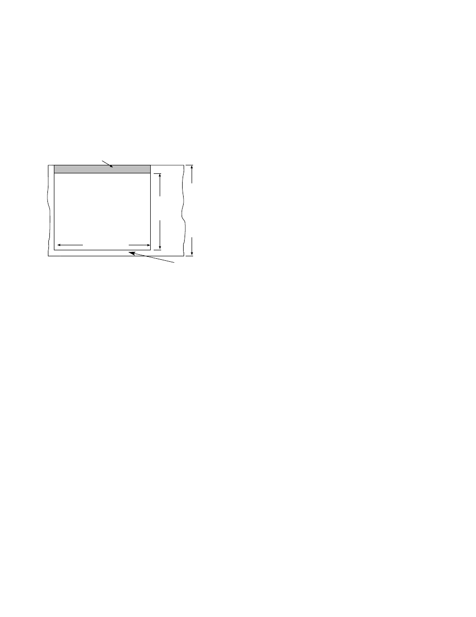
Min.
33"
(839mm)
flat
surface
Shaded area is additional cut-out required for
slide-in installations only
30.375"
(772mm)
38.5"
(978mm)
Plan View
Single-sided dispensers
counter cutout
7
front of counter