Furuno FS-2570 User Manual
Page 26
2-4
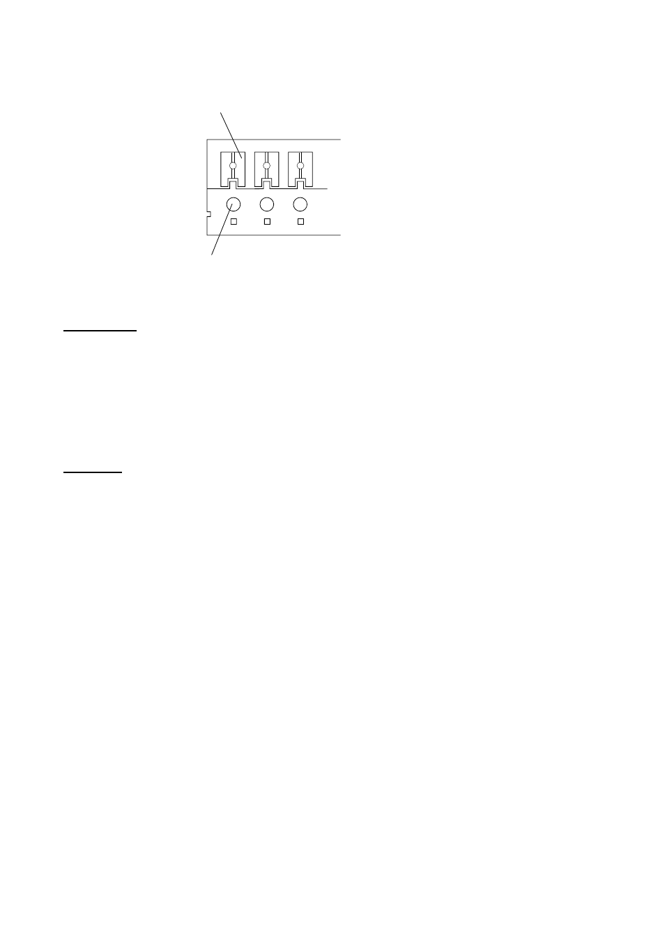
Note1:
How to connect cable to the terminal board.
1. Press this downward by finger or screw driver.
2. Insert a core of cable.
3. Release the finger or screw driver.
Control unit
Connect the transceiver unit and the control unit by the supplied cable with D-sub 15 pin
connector for both ends. The control unit connected to the CONTROLLER 1 port has
priority.
Connect the handset HS-2003 to the HANDSET 1 port at the rear of the control unit. For
other handset or microphone, connect to the HANDSET2/MIC port. Note that these two
ports can not be used at the same time.
Antennas
The antenna for DSC distress (mandatory) and DSC routine frequency (option for FS-2570
only) are connected to the transceiver unit with a 50 ohm coaxial cable, type RG-8/U or
equivalent. Be sure to leave some slack in the cable for future service and maintenance.
Lay the coaxial cable and attach an M-type plug to the cable as follows.
1. Remove the sheath by 30 mm.
2. Bare 23 mm of the center conductor. Trim braided shield by 5 mm and tin.
3. Slide coupling ring onto cable.
4. Screw the plug assembly on the cable.
5. Solder plug assembly to braided shield through solder holes. Solder contact sleeve to
conductor.
6. Screw coupling ring into plug assembly.
7. Screw the plug into the D. ANT (W/R 1) port for DSC distress and ANT (W/R 2 port) for
DSC routine frequency (option) at the bottom of the transceiver unit.