Protector, Series gas fryer chapter 1: service procedures – Frymaster FOOTPRINT 8196345 User Manual
Page 7
1-1
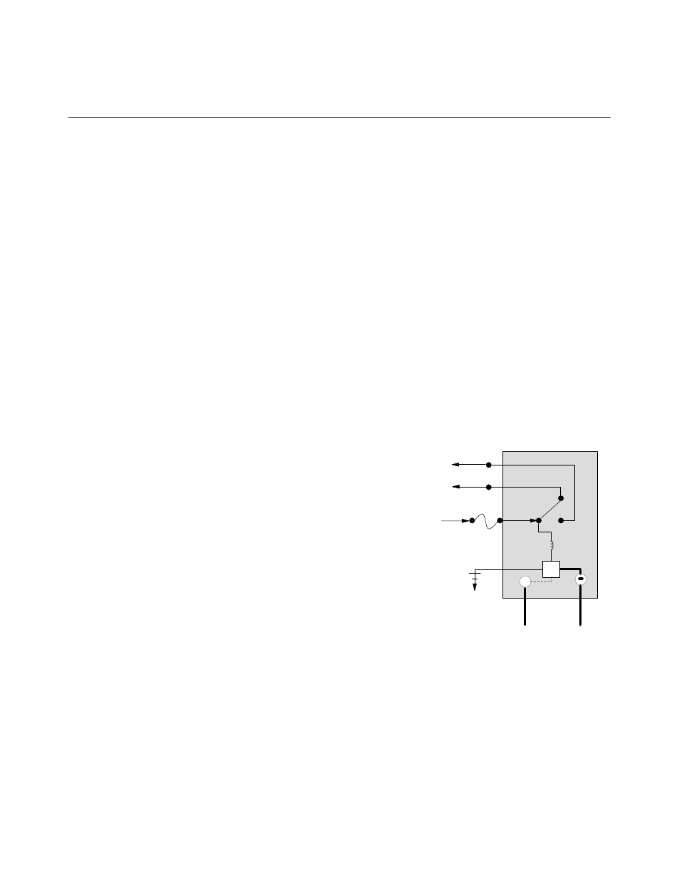
Inside the Ignition Module
TD
Out to
Gas Valve
To Alarm
25 V +
GND
HV
Ignition Wire
Flame Sensor
Coil
PROTECTOR
®
SERIES GAS FRYER
CHAPTER 1: SERVICE PROCEDURES
1.1 Functional
Description
Protector
®
series gas fryers contain a welded stainless steel frypot that is directly heated by a high
efficiency infrared burner system, requiring approximately 43% less energy than conventional
burners to cook the same volume.
Self-contained combustion chambers (referred to as “burners”) are fitted into rails attached to the
sides of the frypot, one on each side. Each combustion chamber is fitted with special ceramic tiles
that are heated by the burning of a forced air/gas mixture. The tiles transfer heat to the frypot by
means of infrared radiation, providing much more constant and uniform heat dispersion over the
surface of the frypot than do conventional burners. Because less heat is lost to the atmosphere in the
process, compared to “open-burner” designs, less fuel is required to achieve and maintain a given
frypot temperature.
In full-vat units, gas flow to both of the burners is regulated by one electromechanical gas valve. All
fryers in this series are equipped with 24 VAC gas valve systems, and all are configured with
electronic ignition.
1.2
The Electronic Ignition System
An ignition module mounted in the component box
(located behind the control panel) is connected to an
ignitor assembly at the burner. The ignition module
performs four important functions: it provides fuse
protection for the 24-volt circuit, provides an ignition
spark, supplies voltage to the gas valve, and proofs the
burner flame. The module contains a four second time
delay circuit and a coil that activates the gas valve. Three
types are in use. A closed-box design is used in most
fryers, but in some fryers built for export, the module
resembles an interface board. A single dual-spark module
is used on current production full-vat fryers.
The ignitor assembly consists of a spark plug, an
enrichment tube, and a flame sensor.
At start-up, the power switch is placed in the ON position, supplying approximately 12-volts DC to
the heat-control circuitry in the computer and to one side of the heat relay coils on the interface
board. If resistance in the temperature probe indicates the temperature in the frypot is below 180ºF
(82ºC), the current flows through a melt cycle circuit where a timer switch alternately closes for six
seconds and opens for 24 seconds. If the temperature is 180ºF (82ºC) or above, the current flows
through a heat circuit, bypassing the timer switch. In either case, ground is supplied to the other leg
of the heat relay coils, which closes electronic switches in the 24 VAC circuit to provide current to
the ignition module. Circuitry in the ignition module sends 24 VAC to the gas valve via a normally
closed high-limit switch and a normally closed drain safety switch. Simultaneously, the module
causes the ignitor to spark for four seconds to light the burner. A flame sensor verifies the burner