Step 2 - installing the ceiling plate, Step 2 - inst – Hunter Fan Hunter Ceiling Fans 41462-01 User Manual
Page 8
8
41462-01 10/14/2005
®
STEP 2 - INST
STEP 2 - INST
STEP 2 - INST
STEP 2 - INST
STEP 2 - INSTALLING THE CEILING PLA
ALLING THE CEILING PLA
ALLING THE CEILING PLA
ALLING THE CEILING PLA
ALLING THE CEILING PLATE
TE
TE
TE
TE
W
W
W
W
WARNING
ARNING
ARNING
ARNING
ARNING
• To avoid possible electrical
shock, before wiring fan,
disconnect power by turn-
ing off the circuit breakers
both to the outlet box and
to its associated wall switch
location. If you cannot lock
the circuit breakers in the
off position, securely fasten
a prominent warning de-
vice, such as a tag, to the
service panel.
1. Drill two pilot holes into the wood
support structure through the
outermost holes on the outlet
box. The pilot holes should be
9/64" in diameter by 2 3/4" in
depth.
2. Thread the lead wires from the
outlet box through the hole in the
middle of the ceiling plate.
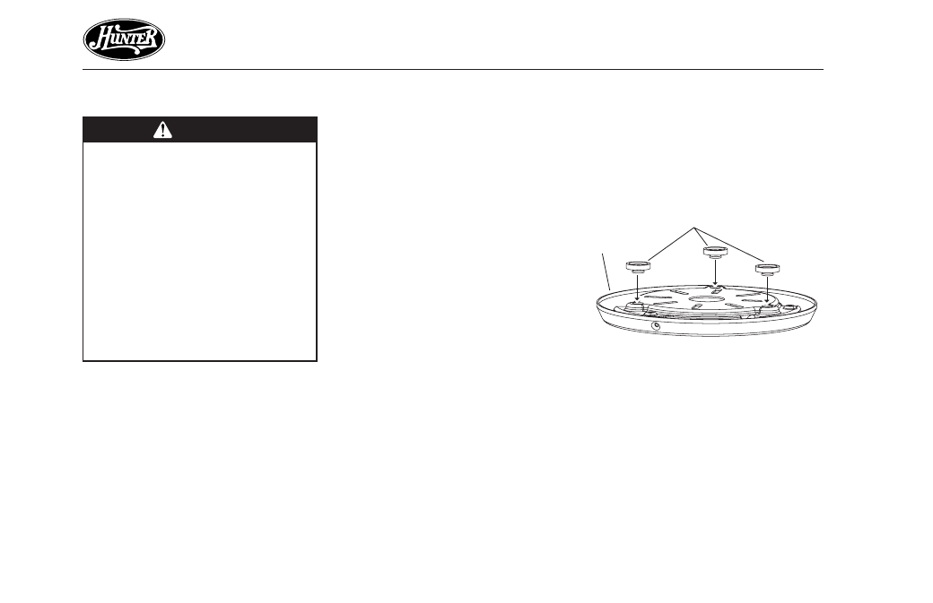
3. Position the three isolators be-
tween the ceiling plate and ceil-
ing by inserting the raised areas
on each isolator into the holes in
the ceiling plate. Refer to Figure
2a.
4. Align the slotted holes in the ceil-
ing plate with the pilot holes in
the wood support structure.
Note: The isolation pads should
be flush against the ceiling.
Figur
Figur
Figur
Figur
Figure 2a - Adding Isolators to
e 2a - Adding Isolators to
e 2a - Adding Isolators to
e 2a - Adding Isolators to
e 2a - Adding Isolators to
Ceiling Plate
Ceiling Plate
Ceiling Plate
Ceiling Plate
Ceiling Plate
Isolators
Ceiling
Plate