Step 9 - remote control – Hunter Fan Hunter Ceiling Fans 41462-01 User Manual
Page 18
18
41462-01 10/14/2005
®
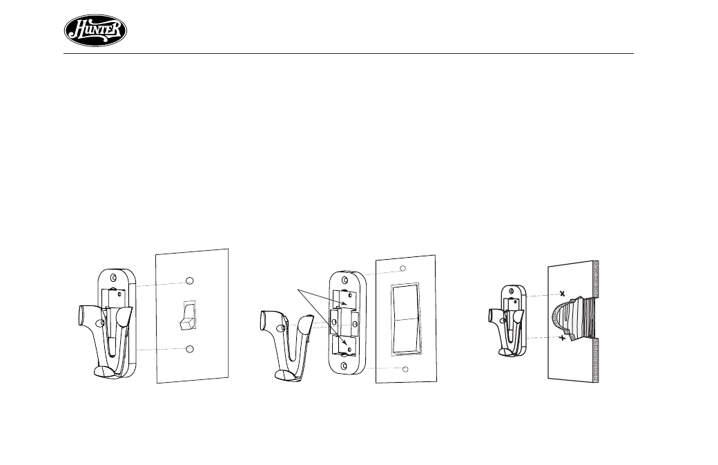
STEP 9 - REMOTE CONTROL
STEP 9 - REMOTE CONTROL
STEP 9 - REMOTE CONTROL
STEP 9 - REMOTE CONTROL
STEP 9 - REMOTE CONTROL
REMOTE CRADLE INST
REMOTE CRADLE INST
REMOTE CRADLE INST
REMOTE CRADLE INST
REMOTE CRADLE INSTALLA
ALLA
ALLA
ALLA
ALLATION
TION
TION
TION
TION
ST
ST
ST
ST
STANDARD LIGHT SWITCH
ANDARD LIGHT SWITCH
ANDARD LIGHT SWITCH
ANDARD LIGHT SWITCH
ANDARD LIGHT SWITCH
1. Remove the two screws holding
the switch cover plate. Do not re-
move the cover plate.
2. Orient the control cradle as
shown in Figure 9a, and line up
the two inner mounting holes
with those on the switch, insert
screws, don't over tighten.
Figur
Figur
Figur
Figur
Figure 9a
e 9a
e 9a
e 9a
e 9a
Figur
Figur
Figur
Figur
Figure 9b
e 9b
e 9b
e 9b
e 9b
ROCKER LIGHT SWITCH
ROCKER LIGHT SWITCH
ROCKER LIGHT SWITCH
ROCKER LIGHT SWITCH
ROCKER LIGHT SWITCH
1. Break off the two tabs by push-
ing outward. See Figure 9b.
2. Remove the two screws holding
the switch cover plate. Do not re-
move the cover plate.
3. Orient the remote cradle as
shown in Figure 9b. Line up the
two outer mounting holes with
those on the switch , insert
screws, don't over tighten.
WALL INST
WALL INST
WALL INST
WALL INST
WALL INSTALLA
ALLA
ALLA
ALLA
ALLATION
TION
TION
TION
TION
1. Locate a 2x4 wall stud in a conve-
nient location.
2. Orient the remote cradle as shown
in Figure 9c, over the 2x4 stud.
3. Use the 1” wood screws in either
the inner or outer mounting holes.
Note:
Note:
Note:
Note:
Note: Wall anchors and 6-32 x 1”
screws may be used in situations
where mounting to a stud is not pos-
sible. Use the inner mounting holes.
Figur
Figur
Figur
Figur
Figure 9c
e 9c
e 9c
e 9c
e 9c
Remove tabs