Compressor – Applied Acoustics Systems Chromaphone 3 Upgrade Acoustic Object Synthesizer Plug-In (Download) User Manual
Page 51
5.4
The Effects Section
51
The
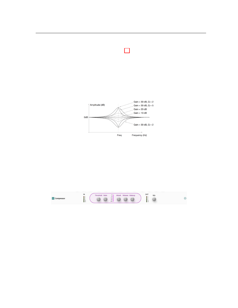
Equalizer
module features two peak filters, labeled
LMF
and
HMF
, allowing to shape the
signal in two frequency bands as illustrated in Figure 27. The filters apply a gain factor to frequency
components in a band located around the cutoff frequency of the filters. This cutoff frequency is
adjusted using the
Freq
knob and can vary between 100 Hz and 10 kHz. The gain factor applied
a the cutoff frequency is controlled by the
Gain
knob and can vary in a
±
15 dB range. When
in its center position there is no attenuation (0 dB). Turning it clockwise boosts the amplitude of
frequencies located around the cutoff frequency while turning it anti-clockwise reduces it. The
Q
knob is used to adjust the so-called quality factor of the filter which controls the width of the
frequency band on which the filter is active. In its leftmost position, the frequency band is wide
and it gets narrower as the knob is turned clockwise.
Figure 27: Peak filter.
The
Gain
knob is used to adjust the output level of this module. In its center position, the level
is left unchanged, it is decreased by turning the knob counter-clockwise and increased by turning
it clockwise.
5.4.2
Compressor
The
Compressor
module is used to automatically compress, in other words reduce, the dynam-
ics of a signal. This module receives two input signals. The first one is the signal to be compressed
while the second one is a control signal which triggers the compression process when it rises above
a given level.
Tuning
The level at which the
Compressor
starts to enter into action is determined by the value of the
Threshold
parameter. This value is in dB and corresponds to the amplitude of the input signal as
monitored by the first level meter of the module.