Assembly of mig system – Kemppi Promig 540R User Manual
Page 9
8 – Promig 540R, Promig 120R/0425
©
KEMPPI
OY
Promig 540R, Promig 120R/0423 – 9
©
KEMPPI
OY
2.4. ASSEMBLY OF MIG SYSTEM
Assemble the units according to the mounting instructions delivered with the unit.
1. Installation of power source
Read paragraph “INSTALLATION” in operation instructions for PRO power sources and
install accordingly.
2. Mounting of PRO power source to transport wagon
P 20
see air-cooled MIG system
P 30W
see liquid-cooled MIG system
P 40
see air-cooled MIG system
3. Put PROMIG onto the power source and lock it with bolts to handles of powersource.
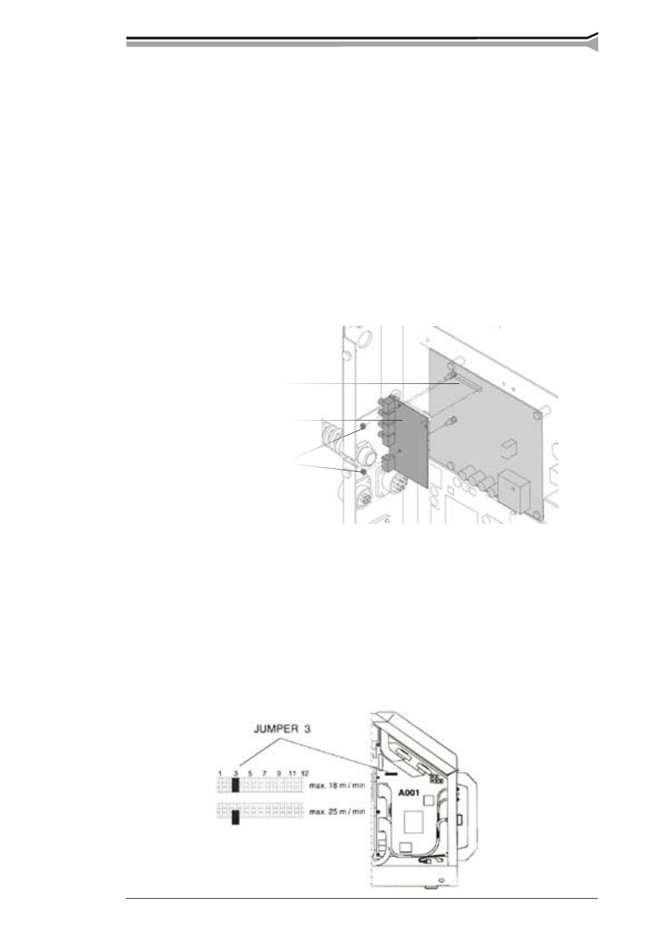
4. Installation of the fieldbus card
MXE 6263504, installation instruction 4279220
Open side plate and install fieldbus card by mounting above the interface card with two M3 nut.
See mounting instructions.
5. Connecting cables
Connect cables according to paragraph ”UNITS, ACCESSORIES, CABLES”.
6. Max. wire feed speed
By delivery, the max. wire feed speed is 18 m/min, which is enough for most welding
applications. If you need a higher speed, you can increase the wire feed speed to 25 m/min
by replacing the gear wheel on motor shaft. The high ratio wheel (*D40*) is delivered with
the feed unit.
Changing the maximum wire feed speed:
– Open side plate and remove JUMPER 3 on control card A001. This alters the tacho
feedback ratio to 0 - 25 m/min
Fieldbus card
M3 nut
Interface card