6 ffc connector pin-out – Interlink Electronics VersaPad PS2 User Manual
Page 14
www.interlinkelectronics.com
12
PS2 VersaPad®
Integration Guide
6.6
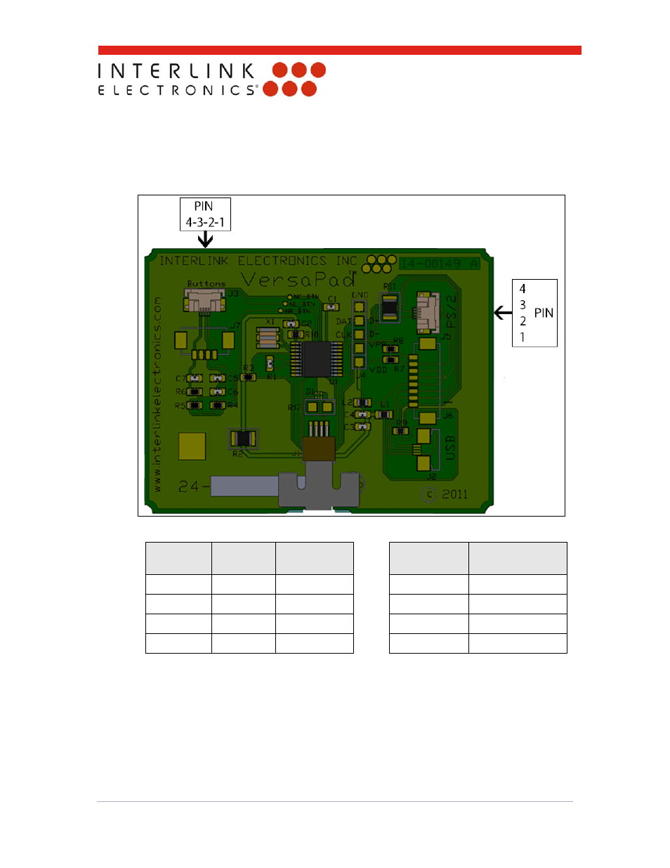
FFC Connector Pin-out
The following figure and table shows the pin-out for Molex header connections to the J5
and J3 components.
Figure 10: FFC Connector Pin-Outs
J5 Pin
Signal
Signal
Description
J3 Pin
Signal
1 VCC +5
V
1
Left
Button
2 CLK Clock
2 Right
Button
3 DATA Data 3
Ground
4 GND
Ground
4 Center
Button
Table 2: J5 & J3 FFC Connector Pin-Outs