Directed Electronics SR6000 User Manual
Page 9
9
9
If optional starter kill relay or its connections are immediately visible upon removal of the under-dash panel,
they can easily be bypassed. Always make the relay and its connections difficult to discern from the factory
wiring! Exposed yellow butt connectors do not look like factory parts, and will not fool anyone! For this reason,
routing the optional starter kill wires away from the steering column is recommended.
The relay satellite wiring carries large amounts of current. The wires should not be extended and should be cut
to the minimum length necessary. Since the relay satellite is functioning as the ignition switch in the vehicle,
it is often convenient to mount the relay satellite close to the main ignition switch harness.
ffiinnddiinngg tthhee wwiirreess yyoouu nneeeedd
Now that you have decided where each component will be located, you’re going to find the wires in the car that
the security system will be connected to.
IIM
MP
PO
OR
RTTA
AN
NTT!! Do not use a 12V test light or logic probe (computer safe test light) to find these
wires! Use a digital multimeter for all testing.
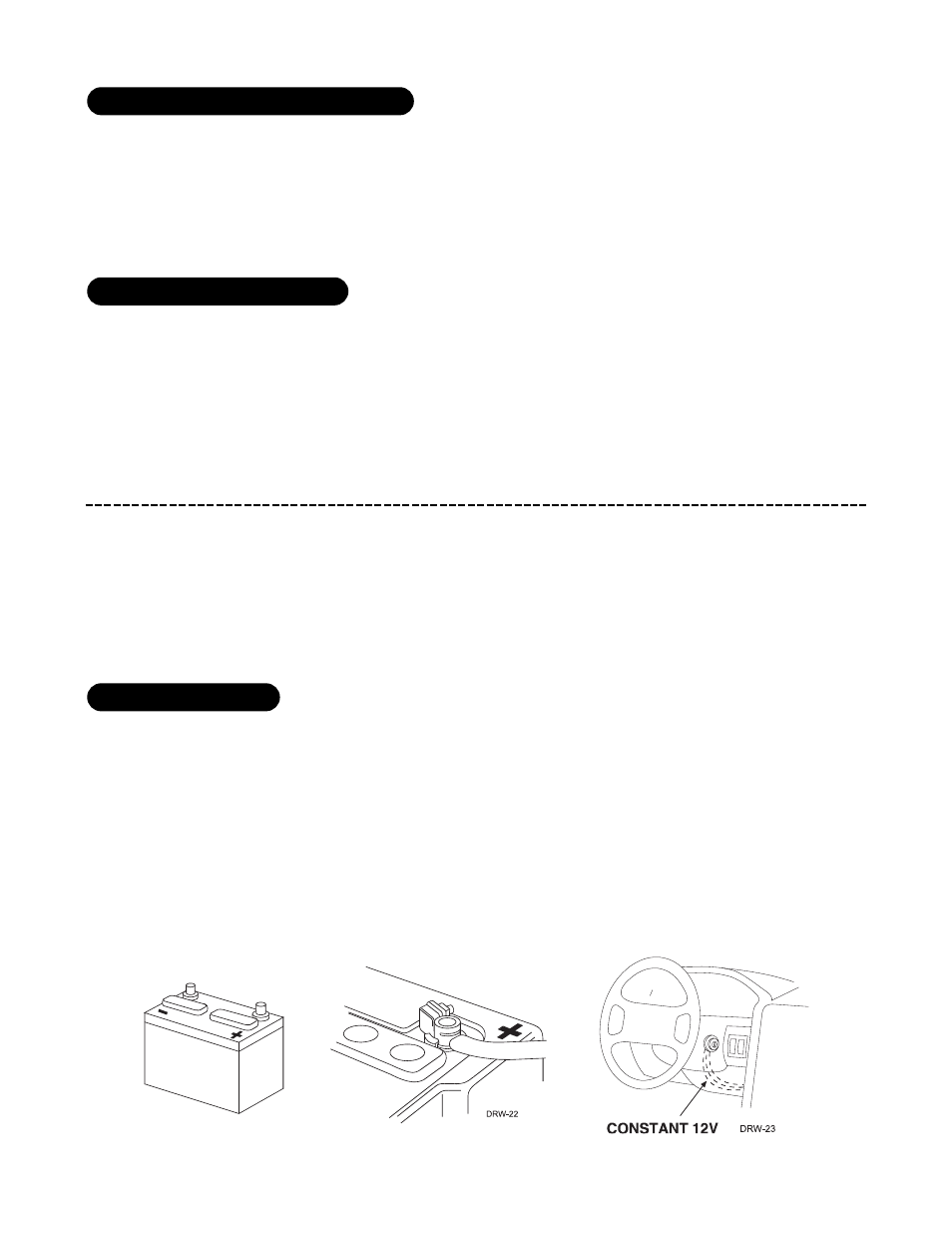
We recommend two possible sources for 12V constant: the (+) terminal of the battery, or the constant supply to
the ignition switch. Always install a fuse within 12 inches of this connection. If the fuse also will be powering
other circuits, such as door locks, a power window module, a Nite-Lite® headlight control system, etc., fuse
accordingly.
IIM
MP
PO
OR
RTTA
AN
NTT!! Do not remove the fuse holder on the red wire. It ensures that the control module
has its own fuse, of the proper value, regardless of how many accessories are added to the main
power feed.
oobbttaaiinniinngg ccoonnssttaanntt 1122VV
llooccaattiioonnss ffoorr tthhee rreellaayy ssaatteelllliittee
llooccaattiioonnss ffoorr tthhee ooppttiioonnaall ssttaarrtteerr kkiillll rreellaayy