Warning, Caution, Important – Leslie Controls NYC Heat Exchanger User Manual
Page 7: A. installation, B. pipe connections, C. electrical connections
Page 7 of 25
A.
INSTALLATION
After connecting inlet cold water, outlet hot water, Steam
inlet, re-circulation inlet, safety relief valve drains and
condensate piping, lag unit to concrete floor.
B. PIPE CONNECTIONS
Connection
Drawing symbol
Inlet water
M
Outlet Hot water
N
Inlet Steam
L
Re-circulation Inlet
P
Condensate Outlet
R
Model
Connection
Conn. Size
Inlet water
2” F NPT
Outlet Hot water
2” F NPT
Inlet Steam
4” RF
NYCHA60
Outlet Condensate
¾”F NPT
Inlet water
2” F NPT
Outlet Hot water
2” F NPT
Inlet Steam
4” RF
NYCHA90
Outlet Condensate
¾”F NPT
Inlet water
2” F NPT
NYCHA120
Outlet Hot water
2” F NPT
Inlet Steam
4” RF
Outlet Condensate
¾”F NPT
Inlet water
2” F NPT
Outlet Hot water
2” F NPT
Inlet Steam
4” RF
NYCHA150
Outlet Condensate
¾”F NPT
C.
ELECTRICAL CONNECTIONS
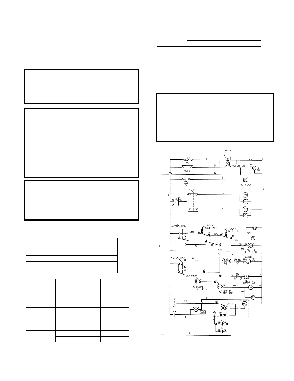
See drawing for latest revision of wiring.
Figure 4 – Leslie Electrical Schematic
WARNING!
ELECTRICAL SHOCK HAZARD
Be certain that all connections are secure and the
conduit box cover is closed before electrical power is
connected. Failure to follow these instructions could
result in serious personal injury, death and/or property
damage.
CAUTION!
Safety Relief valves and condensate drain must be
connected properly to drainage, to insure no hot water
can contact people.
CAUTION!
Water pressure must be supplied slowly to the inlet of
the unit so that the solenoid valves are pressurized
correctly. If not, then correct temperature adjustment
may not be possible.
IMPORTANT!
1.
Shut off cold water valves to secondary blend
valves.
2.
Insure that cold water supply to primary blend
valves is turned on.
3.
Slowly supply water pressure to primary blend
valves after full water pressure is reached then
open up cold water supply to secondary blend
valves slowly.
4.
Slowly supply steam to unit, up to 8 psig.