Wiring terminals, Enrolling – Interlogix NX-1710E User Manual
Page 6
NX-1710E Single Door Control
6
III.
WIRING TERMINALS
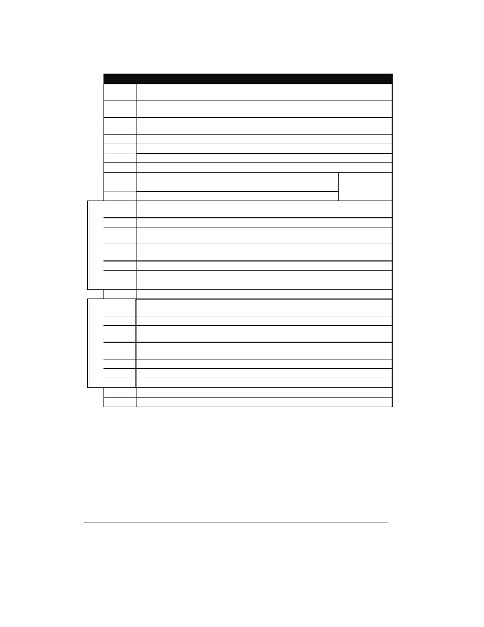
To install the door control, simply wire it into the system. Refer to the following wiring table for details.
For the purpose of these instructions, the term “door control” refers to the NX-1710E module, and
the term “reader” refers to the specific card reader attached to the system.
IV.
ENROLLING
The NetworX control panels have the ability to automatically find and store in memory the presence of all
keypads, zone expanders, wireless receivers, output modules, and any other device on the keypad buss. This
allows these devices to be supervised by the control panel. To enroll the devices, enter the Program Mode
using the procedure outlined in the control panel Installation Manual. When the Program Mode is exited, the
NX-8 control will automatically enroll the devices. The enrolling process takes about 12 seconds, during which
time the Service LED will illuminate. User codes will not be accepted during the enrolling process. Once a
module is enrolled, if it is not detected by the control, the Service LED will illuminate.
DESCRIPTION
DATA
Connect to the NetworX control panel DATA terminal. Data-signaling terminal to all the
devices on the bus.
COM
Connect to the NetworX control panel COMMON terminal. Supplies the common side of the
power to the door control module.
POS
Connect to NetworX control panel AUX POWER + terminal. Supplies power to the door
control module.
+12 Power to reader module, if required.
+5 Power to reader module, if required.
COM Connect to common terminal of box tamper.
TMPR Box Tamper
N/C Normally closed relay contact to activate door strike.
C Closed relay contact to activate door strike.
N/O Normally open relay contact to activate door strike.
Rating:
5A 125, 277V AC
5A 30V DC
A-EG
Egress input. To use this feature, connect the normally open egress switch between this
terminal and COM.
A-TM
Tamper input (from Reader “A”)
A-LR
Red LED (
LED2
) control (to Reader “A”). Relay. If available, connect to LED control on
reader.
A-LG
Green LED (
LED1
) control (to Reader “A”). Relay. If available, connect to LED control on
reader.
A-BZ
Buzzer control (to Reader “A”).
A-D1
Wiegand Data 1 terminal (from Reader “A”).
Read
er “
A
”
A-D0
Wiegand Data 0 terminal (from Reader “A”).
COM Common dry contact
B-EG
Egress input. To use this feature, connect the normally open egress switch between this
terminal and COM.
B-RM
Tamper input (from Reader “B”)
B-LR
Red LED (
LED2
) control (to Reader “B”). Relay. If available, connect to LED control on
reader.
B-LG
Green LED (
LED1
) control (to Reader “B”). Relay. If available, connect to LED control on
reader.
B-BZ
Buzzer control (to Reader “B”).
B-D1
Wiegand Data 1 terminal (from Reader “B”).
Read
er “
B
”
B-D0
Wiegand Data 0 terminal (from Reader “B”).
COM Common terminal.
DOOR Door contact (requires 3.3K end-of-line resistor).