Panasonic NV-G25 Series User Manual
Page 7
Attention! The text in this document has been recognized automatically. To view the original document, you can use the "Original mode".
INSTALLATION, TUNING
THE TV SET TO THE VIDEO
PLAYBACK CHANNEL
® ® @ ®
m
Q
O ©
1—1 T
COLOUR—I
f
AUTO------------ 1
TEST—-----------
COLOUR/
TEST SIGNAL
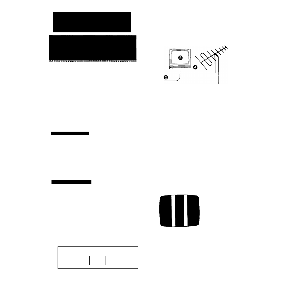
Connection to a TV Set
0 Connect the external aerial to the RF Input Socket on
the VTR.
^11^ @ Connect the aerial terminal on your TV set to the RF
Output Socket on the VTR with the supplied DIN-DIN
Coaxial Cable.
0 Connect the AC Mains Lead (Supplied) to the AC
Mains Socket of the VTR, and a mains outlet.
Video Playback Channei
0 Turn the TV set on.
0 Press the VTR On/Off Switch to turn the VTR On.
(FRONT PANEL)
^
N
VTR
•The indicator will light up.
0
Set the VTR/TV Selector to “VTR”.
(FRONT PANEL)
i
VTRTTV
\____________________
J
►VTR Indicator will appear in the Multi-Function Display.
NV-G25A;
FOR YOUR SAFETY
Install any external aerial to AS 1417.1.
-Video Playback Channel Selector [NV-G25A, EA]
This switch is used to select the Video Playback channel
which is not occupied with any TV station. [NV-G25A: 0 or
1: NV-G25EA: 2 or 3].
RF Signal Level Switch:
Used to attenuate the reception of the VHF and/or UHF
aerial signals.
If the reception is normal, set to “HIGFt”. If the signal is
strong {stripes appear in the upper part of the picture), set
to “LOW".
0 Set the Colour Mode/Test Signal Switch to “TEST".
(REAR PANEL)
COLOUR
AUTO^
TEST
COLOUR/
TEST SIGNAL
0
Tune the selected programme position (channel) of the
TV set to the VHF channel shown below for your
model. Confirm on the TV set that the received test
pattern is as shown below.
NV-G25A
VHF channel 0 or 1*
NV-G25EA
VHF channel 2 or 3
NV-G25A only
*ln some areas chan
nel 0 may be used by
local TV station. In
this case switch to
channel 1.
0
Set the Colour Mode/Test Signal Switch to “AUTO".
Your TV is now ready to receive the RF output signal
from the VTR.
0 To check.
Playback pre-recorded tape.
•If, during recording or playback, the colour is not
satisfactory, it can be stabilized by setting Colour
Mode/Test Signal Switch to COLOUR.