Industrial Injection LB7 Dual CP3 User Manual
Page 4
Dual Fueler CP3 Pump Kit for LB7
Dual Fueler CP3 Pump Kit for LB7
4
5
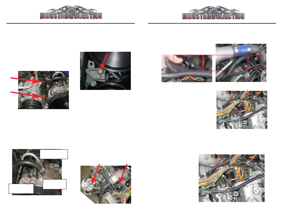
8. Attach lines by part
number as shown below:
#3
: Return
Line
#4
: High Pres-
sure Line
#2
: Inlet Fuel
Line
10. Cut back rubber sleeve
B
. Cut
stock fuel supply line
and insert
supplied
#2
1/2”x1/2”x3/8” ‘T’ connector in between 1/2” fuel
supply line, secure with
#10
1/2” hose clamps.
9. Follow flow direction
arrow
A
exiting from fuel
filter housing in order to
locate fuel supply hose
B.
A
B
11. Locate Stock CP3 Pump
C
and
locate stock return line
D
from Stock
CP3 Pump. Cut rubber hose and insert
#3
5/16”x5/16”x5/16” ‘T’ connector.
Use
#11
hose clamps to secure.
C
D
Now all 3 lines should be connected to the Dual Fueler Pump and
to the engine in the correct spots.
12. Locate Stock CP3
Pump
C
from step 11,
and locate electronic
control wire harness
E
.
Unplug wire Harness
E
.
E
13. Plug Wire Harness
E
into
#13
, then plug other
end of
#13
back into
Stock CP3 Pump
C
.
6. Install 1 factory A/C Bolt that
you removed from top of A/C
Unit into bottom of Dual Fueler
bracket.
5. Place A/C Compressor back into
original position. Place
#6, (Dual
Fueler Assembly bracket with pump)
on top of the Right A/C Compressor
bolt holes and use
#12 bolts
to attach
Dual Fueler Bracket Assembly to A/
C Compressor, torque 37 lb ft. Save
1 original A/C bolt for the next step.
7. Then torque
#4 high pressure line nut
on both ends to 30 ft lb.
Re-install
Water Line W See figure 4 on step 4
.