Industrial Injection LB7 Dual CP3 User Manual
Page 3
Dual Fueler CP3 Pump Kit for LB7
Dual Fueler CP3 Pump Kit for LB7
16. Remove Fuse box Cover
F
and
place
#1
(Control Module) as shown to
the right.
#1
(photo is taken from the drivers
side of the vehicle)
18. Replace fuse box cover
F
,
taking care of not to pinch harness,
and re-assemble stock parts
G
and
H
as shown in step 15.
6
3
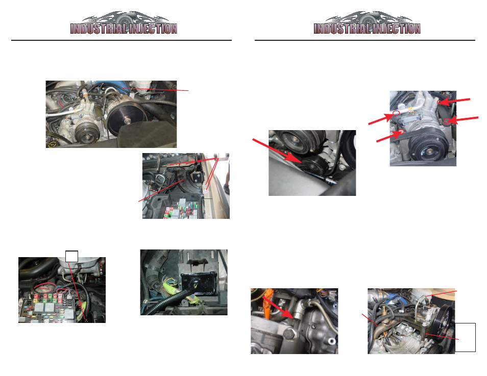
1. 02-04 Models: Remove belt and
Install
#5
Idler Pully
in existing
threaded hole on engine bracket as
shown below. Torque to 27 lb ft.
01 Models refer to appendix C.
2. Remove
4 A/C Bolts
as shown and
set
A/C compressor
to the left of the
engine to access fuel rail below.
Fig. 1
Fig. 2
3. Remove plug from end of fuel
rail with a TB50 Torx wrench or
socket and install
#7, Fuel Rail
Fitting
.
I
mportant: Early Model LB7
trucks may have a block off
plate behind torx plug fitting, if
so Remove this block off plate
and drill out to same size as sup-
plied fuel rail adapter fitting.
Fig. 3
17. Secure
#1
with
#19
screws
as shown below.
14. Route
#1
, (Control Module) Wiring from Stock CP3 Pump
C
as
shown and attach to other wiring with
#18
(tie straps). Connect
#14
to
back of Dual Fueler CP3 Pump.
15. Temporarily remove Metal Support
G
as shown by removing 4 bolts
H
and set
aside to remove fuse box cover
F
.
#1
will
be tucked inside fuse box cover
F
.
G
F
H
Wire Routing
4. Remove Water Line
W
so to
access the
#4 steel high perssure
line
when
A/C compressor
is
placed back and
Dual Fueler
is
installed.
Then attach
#4, Steel high
pressure line
, BUT DO NOT
TORQUE IT YET! Route it so it
will lay under
A/C compressor.
Ignore
this
spacer
W
#4
First: Install “Dual Fueler” bracket
and pully if not assembled on
pump. Refer to Appendix B on
page 8.