Assembly, Install mower and drtve belt (see figs. 4 and 7), Check for proper position of all belts – Craftsman 917.258692 User Manual
Page 9
Attention! The text in this document has been recognized automatically. To view the original document, you can use the "Original mode".
ASSEMBLY
INSTALL MOWER AND DRtVE BELT
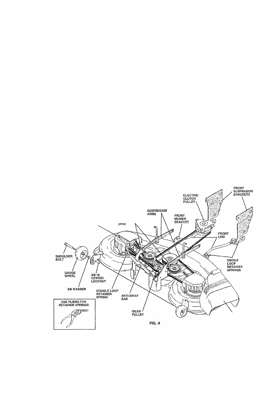
(See Figs. 4 and 7)
Ba sure iraclor is on level surface and mower sospenston
arms are raised with aitachmeni lift conirol,. Engage park
ing brake.
•
Cut and remove ties securing anti-sway bar and balls.
Swing anti-sway bar to left side of mower deck.
•
Slide mower undartractor with discharge guard to right
side of tractor,
IMPORTANT: CHECK SEIT FOR PROPER ROUTING IN
ALL MOWER PULLEY GROOVES. INSTALL BELT INTO
ELECTRIC CLUTCH PULLEY GROOVE.
•
Install one front link In top hole of the H.H., front mower
bracket and R.H. front suspenatoh bracket. Retain
with two single loop retainer springs as shown
•
Install second iron! link In L. H, front suspenslort bracket
only and retain with single loop retainer spring as
shown.
•
Turn height adjustment knob counterclockwise until it
stops
» Lower mower linkage with aitachmeni lift control.
•
Place the L.H, suspension arm on outward pointing
deck pin. If necessaty, rock and raise front of mower
to align deck pin wlln the hole in suspension arm
Retain with double loop retainer spring with loops
down as shown,
Slide left side oi mower back a nd install the unattached
front link in top hots of the LH, front mower bracket.
Retain with single loop retainer spring as shown
DOUBLE LOOP
rtSTAlNEB SPRING
(OUlWJircl pOPRilnp
deck ■ '
•
Place the R.H suspension arm on outward pointing
deck pin. if necessary, rock and raise front of mower
to align deck pin with the hols in suspension arm.
Retain with double loop retainer spring with loops down
as shown
•
Connect anti-sway bar to chassis bracket under left
footrest and retain with double loop retainer spring
•
Turn height adjustrrrent knob cloclcwlss to remove
slack from mower suspension.
•
Raise mower to highest position.
•
Assemble gauge wheels (See ”TO ADJUST GAUGE
WHEELS" in the Operation ssction of this manual).
CriBC^fv MOwvBiFt lf#BVBL-NBoS
For best cutting results, mower should be property leveled,
See “TO LEVEL MOWER HOUSING" in the Service and
Adjustments section of this manual.
CHECK FOR PROPER POSITION OF ALL
BELTS
See the figures that are shown for replacing motion, mower
drive, and mower biada drive belts in the Service and
Adjustmenis section of this manual Verify that the belts
are routed correctly
DISCHARGE GUARD