Service and adjustments – Craftsman 917.258692 User Manual
Page 23
Attention! The text in this document has been recognized automatically. To view the original document, you can use the "Original mode".
SERVICE AND ADJUSTMENTS
TO REPLACE MOWER BLADE DRIVE BELT
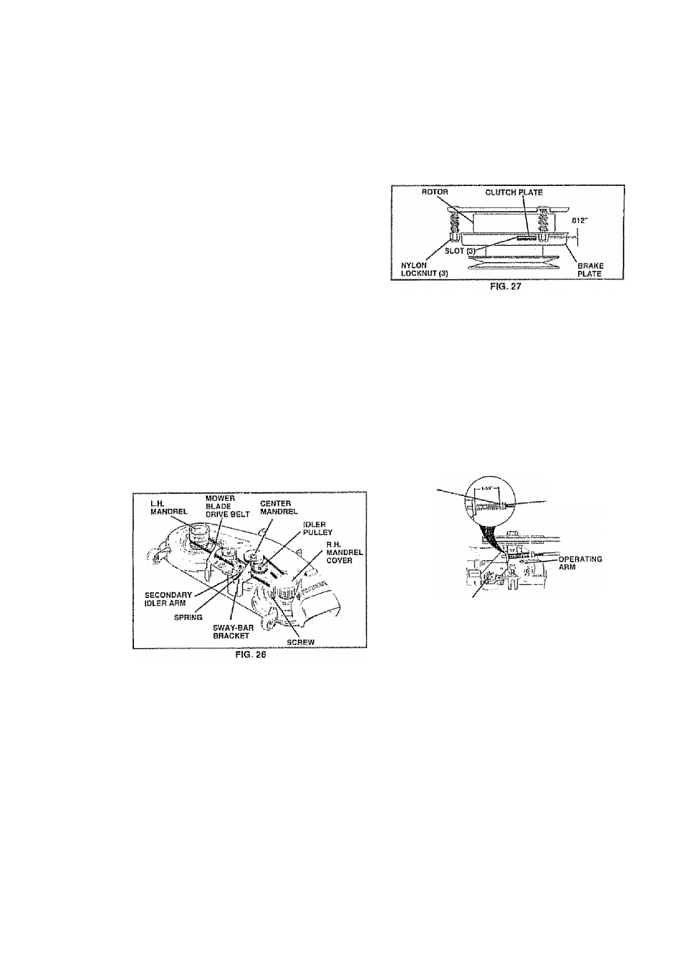
(See Fig. 26)
Park Ite tractor on level surface Engage parking brake.
Remove mowerdrJ ve belt (See ‘TO REPLACE MOWER
DRIVE BELT" In this section of this manual),
Remove mawer (See TO REMOVE MOWER" in this
section of this manual).
Remove four screws from R H, mandrel cover and
remove cover Unhook spring from bolt on mower
housing,
Carefully roll belt off R,H, mandrel pulley.
Remove belt from center mandrel pulley, idler pulley,
and L.H. mandrel pulley
Remove any dirt or grass which may have accumu-
iated around mandrels and entire upper deck surface.
Check secondary idler arm and Idler fo see that they
rotate freely.
Be sure spring is hooked in secondary Idler arm and
sway-bar bracket
Install newbeJt in lower groove of L.H, mandrel pulley,
Idler puliey, and cenler mandrel puiley as shown
Roil belt over R..H, mandrel pulley Make sure belt Is In
all grooves properly
Reconnect spring to bolt in mower housing and reln-
statl R H - martdre! cover,
Reinstall mower to tractor (See "INSTALL MOWER
AND DRIVE BELT' in the Assambly section of this
manual).
.
Reassemble mower drive belt (See "TO REPLACE
MOWER OfliVE BELT in this section Of this manual).
TO ADJUST BRAKE (See Fig. 28)
Your tractor is equipped with an adjustable brake system
which is mounted on the side of the iransaxie,
!f tractor requires mors than six (6) feet stopping distance
athigh speed in highest gear, then brake must be adjusted
•
Depress clutch/braks pedal and engage parking brake.
•
Measure distance between brake operating arm and
not “A"
0(1
brake rod.
•
I f distance Is other than 1 -3/4”, loosen jam nut and turn
nut "A“ until distance becomes 1-3/4" Retighten jam
nut against nut "A".
•
Road test tractor fo rproper stopping distance as stated
above. Readjust it necessary. If stopping distance is
still greater than six (6) (eel In highest gear, further
maintenance is necessary. Contact your nearest au
thorized service center/departmenl.
WITH PARKIMe BRAKS "ENGAGED"
NUT ‘ A‘‘
JAM NUT
DO NOT TOUCH THtS NUT Г FOHTMEB SRAKE ADJUST
MENT tS NECESSARY CONTACT YOUR NEAREST AUTHO
RIZED SERVICE GEHTEFmEPARTMENT
TO ADJUST ATTACHMENT CLUTCH (See
Fig. 27)
The electric clutch should provide years of service. The
clutch has a built-in brake that stops the pulley within 5
seconds. Eventually, the internal brake will wear which
may cause the mower blades to not engage, or, to not stop
as required, Adjusiments should be made by your nearest
authorized service center/department
•
Make sure attachment dutch and ignition switches are
in "OFF position,
•
Adjust the three nylon locknuts until space between
clutch plate and rotor measures ,012“ at all three slot
locations cut in the side of brake plate.
NOTE: Affsr installing a new electric clutch, run tractor at
full throttle and engage and disengage eteclrtc dutch 10
cycles to wear In dutch plats,
23
FIG, 28
TO REPLACE MOTION DRIVE BELT
(See Fig. 29)
Park the tractor on level surface Engage parking brake
For assistance, there Is a belt installation guida decal on
bottom side of left footrest
•
Remove trtower (See ‘TO REMOVE MOWER" in this
section of this manual )
•
Disconnect dutch wire harness
•
Remove dutch locator.
•
Remove upper belt keeper.
•
Remove bail from stationary idier and ciutching Idiar.
•
Puli bait slack toward rear of tractor. Carefully remove
belt upwards from transmission input puiley and over
cooling fan blades
•
Pull belt toward frontof tractor and remove downwards
from around electric clutch
•
Install new belt by reversing above procedura