Acuum, Witch, Djustment – Wood’s Powr-Grip P11104AC User Manual
Page 22
Rev 10.0/6-12
20
P1-AC: #35110
V
ACUUM
S
WITCH
A
DJUSTMENT
Vacuum Switch Function
A vacuum sensor/electrical switch assembly controls the low vacuum warning light. The power switch
activates the warning light and the vacuum pump, which evacuates the vacuum pads.
13
After the lifter
attains a vacuum level sufficient for lifting the maximum load weight (hereafter, “minimum lifting level”),
the vacuum switch automatically turns off the warning light. When vacuum decreases to a level that is
lower than the minimum lifting level (as when releasing a load), the vacuum switch automatically turns on
the warning light again, until the minimum lifting level is regained.
Conditions Requiring Readjustment
At the factory, the vacuum switch is set to the minimum vacuum level specified for the Load Capacity (see
SPECIFICATIONS). However, shipping vibrations or shocks, normal wear, or other conditions may
adversely affect this adjustment. Periodically verify the switch adjustment by comparing how the low
vacuum warning light functions in relation to the vacuum level registered on the vacuum gauge, as
follows:
• If the warning light does not
turn off after
vacuum increases to a level much
higher
than the minimum
lifting level, the vacuum switch may be adjusted to turn off the warning light at a lower vacuum level.
Otherwise, the operator might wait unnecessarily for the warning light to turn off, after the lifter has
already attained sufficient vacuum to lift the maximum load weight.
• If the warning light does not
turn on before
vacuum decreases to a level
lower
than the minimum lifting
level, the vacuum switch
must be adjusted to turn on the warning light at a higher vacuum
level
.
14
Otherwise, the warning light would not alert the operator that the vacuum level is insufficient
to lift the maximum load weight.
Adjustment Procedure
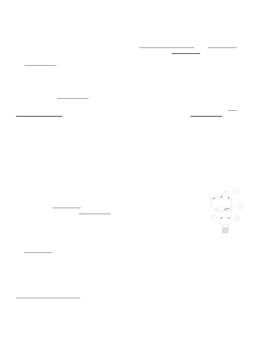
1) Using a 1/4" open-end wrench (as provided), turn the adjustment screw about
1/6th turn at a time (approximately one flat of the screw head).
To make the warning light
turn off
at a
lower
vacuum level, turn the screw
clockwise
(when viewing vacuum switch from end with electrical connectors).
To make the warning light
turn on
at a
higher
vacuum level, turn the screw
counter-clockwise
(when viewing vacuum switch from end with electrical
connectors).
2) Recheck the vacuum switch setting following each 1/6th turn of the
adjustment screw. In order to test the adjustment accurately, release the
vacuum pads completely before reapplying them to a test surface.
When the vacuum switch is adjusted correctly, the warning light turns off
only
after
vacuum increases to a level higher than the minimum lifting level; and the warning light
turns on again
before
vacuum decreases to a level lower than the minimum lifting level.
13
If the warning light does not turn on when the power switch is placed in the “ON” position, the light bulb may be burned out.
Replace the bulb when necessary.
14
In order to observe lifter functions while vacuum is decreasing, it may be necessary to create a controlled leak in the vacuum
system (eg, by breaking the seal between one or more vacuum pads and the test surface).
1 ELECTRICAL CONNECTORS
2 ADJUSTMENT SCREW
3 LIGHT ON AT HIGHER VACUUM
4 LIGHT OFF AT LOWER VACUUM