Pply the, Ads to a – Wood’s Powr-Grip P11104AC User Manual
Page 10
Rev 10.0/6-12
8
P1-AC: #35110
T
O
A
PPLY THE
P
ADS TO A
L
OAD
Powering up the Lifter
With the valve handle in the “RELEASE” position, place the power switch in the "ON" position.
This energizes the vacuum pump and the red low vacuum warning light (see Load Capacity and
the Warning Light to follow).
5
WARNING: Never turn power off during operation; keep pump running
throughout lift.
The lifter is designed for the vacuum pump to run continuously. Placing the power switch in the
"OFF" position during lifter operation could result in the release of the load and possible injury to
the operator (see T
O
L
IFT AND
M
OVE THE
L
OAD
: In Case of Power Failure to follow).
Positioning the Lifter on the Load
Make certain that the contact surfaces of the load and all vacuum pads are free of any
contaminates that could prevent the pads from sealing against the load (see MAINTENANCE:
V
ACUUM
P
AD
M
AINTENANCE
).
Center the lifter’s rotation axis to within 2" [5 cm] of the load center, since off-center loading can
cause the load to rotate or tilt unexpectedly (see T
O
R
OTATE THE
L
OAD
E
DGEWISE
or T
O
T
ILT THE
L
OAD
to follow), and it may also damage the lifter.
6
Make sure that all vacuum pads will fit entirely on
the load’s contact surface (see SPECIFICATIONS: Pad Spread) and that they will be loaded
evenly while lifting (see SPECIFICATIONS: Per-Pad Load Capacity). Then apply the lifter to the
load so that all pads are touching the contact surface.
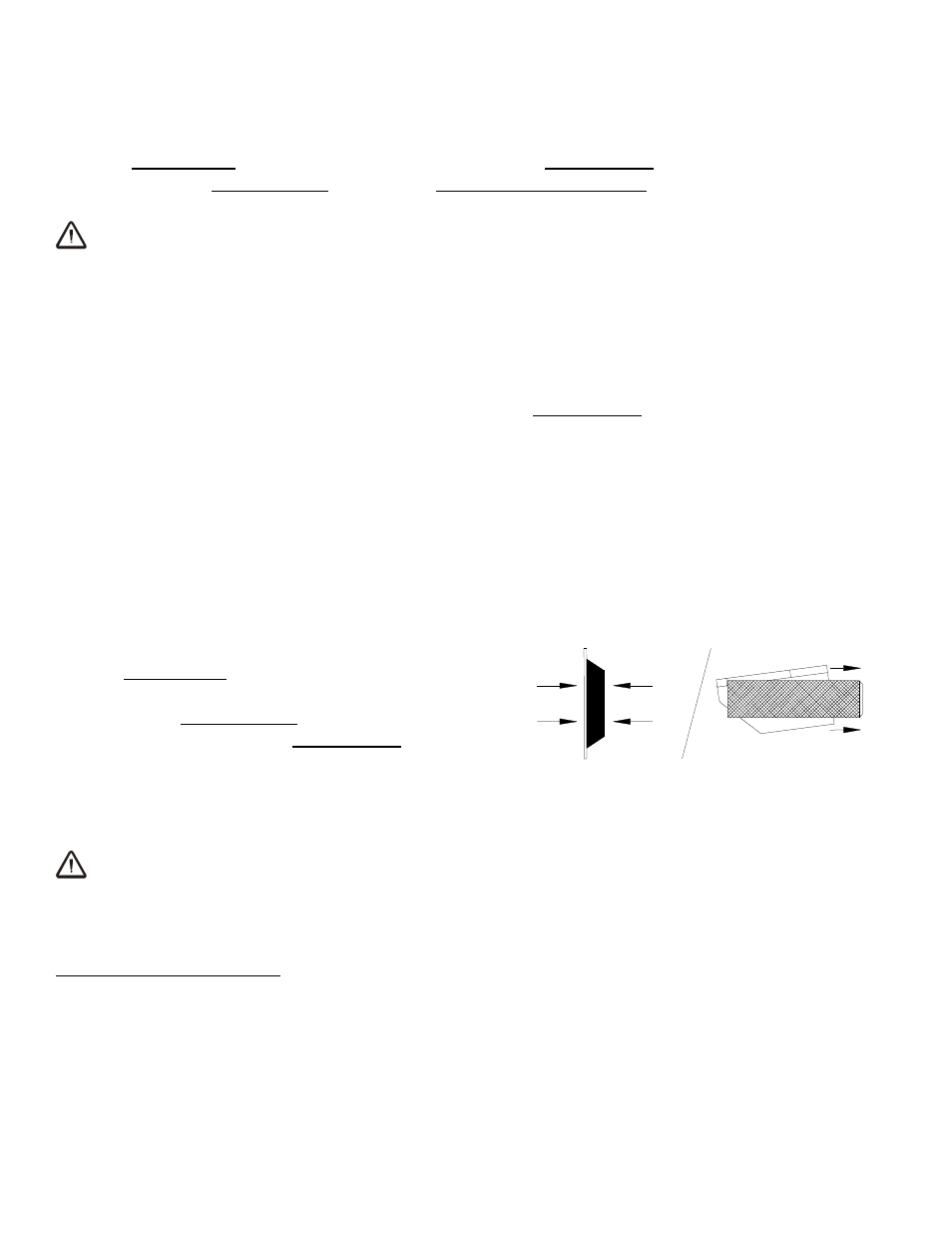
Sealing the Pads against the Load
Pull the valve handle outward to the “APPLY” position.
This opens the lifter’s vacuum lines to the vacuum flow
created by the vacuum pump. Firm pressure at the
center of the lifter helps the vacuum pads begin to seal
against the load.
The valve handle must remain in the “APPLY” position
throughout the entire lift. Any interruption of the vacuum flow during lifter operation could result
in the release of the load and possible injury to the operator.
WARNING: Keep valve handle in “APPLY” position throughout lift.
Note: If a vacuum pad has been lying against a hard object (as during shipping), it may be
slightly distorted. Although initially it may be difficult to apply the pad to a load, this condition
should correct itself with continued use.
5
If the vacuum pump or any other powered component fails to function while the power switch is in the "ON" position, make
sure the lifter is connected correctly to an appropriate power source, as directed in the ASSEMBLY section. If so, examine the
circuit breaker (see OPERATING FEATURES) to determine whether it has interrupted the electrical circuit to the component.
Although the operator can reset the circuit breaker, the power interruption may indicate an electrical problem that requires
attention. Correct any deficiency before resuming normal operation of the lifter (see wiring diagram provided).
6
The lifter is designed to handle the maximum load weight (see SPECIFICATIONS: Maximum Load Capacity) when the load’s
center of gravity is positioned within 2" [5 cm] of the lifter’s rotation axis. Occasional loading deviations are permissible, provided
that the operator can maintain control of the load at all times and that the load weight is low enough to avoid damaging the lifter.
TO APPLY