5 connecting via the k-net, Wiring the cat 5 line in/line out rj-45 connectors, Connecting via the k-net – Kramer Electronics TP-107AVR User Manual
Page 20: Figure 12: cat 5 pinout, Figure 13: wiring the rs-485 connector, Table 9: cat 5 pinout, Nout is defined in, Table 9, Figure 12, Ined in
Configuring a TP-107AVR System
17
17
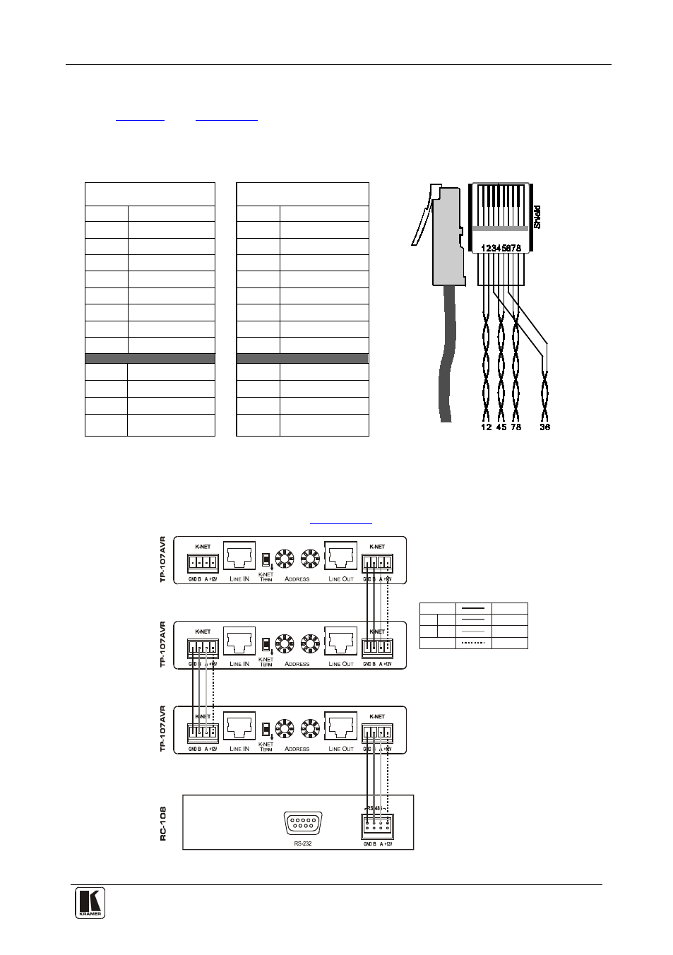
5.4 Wiring the CAT 5 LINE IN/LINE OUT RJ-45 Connectors
define the STP CAT 5 PINOUT, using a straight
pin-to-pin cable with RJ-45 connectors:
Figure 12: CAT 5 PINOUT
Table 9: CAT 5 PINOUT
EIA /TIA 568A
EIA /TIA 568B
PIN
Wire Color
PIN
Wire Color
1
Green/White
1
Orange/White
2
Green
2
Orange
3
Orange/White
3
Green/White
4
Blue
4
Blue
5
Blue/White
5
Blue/White
6
Orange
6
Green
7
Brown/White
7
Brown/White
8
Brown
8
Brown
Pair 1 4 and 5
Pair 1 4 and 5
Pair 2 3 and 6
Pair 2 1 and 2
Pair 3 1 and 2
Pair 3 3 and 6
Pair 4 7 and 8
Pair 4 7 and 8
5.5 Connecting via the K-NET™
The TP-107AVR units connect to the RC-108/RC-116 controller via the
K-NET ports, as illustrated in
Figure 13: Wiring the RS-485 Connector
K-NET PINOUT
GND
Green
Black
Red
White
+12V
+
-
B
A