Rj-45 pinout assignments – Allied Telesis AT-FS238b/2 User Manual
Page 51
AT-FS238a/x and AT-FS238b/x Series Installation Guide
41
RJ-45 Pinout Assignments
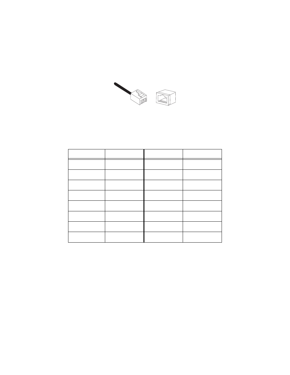
Figure 19 shows the pin assignments of the RJ-45 connector.
Figure 19 RJ-45 Pin Assignments
Table 10 lists the 10Base-T/100Base-TX connector pins and their signals
when the port is operating in either MDI or MDI-X configuration.
Table 10 RJ-45 Pinouts
MDI-X
Signal
MDI
Signal
1
RX+
1
TX+
2
RX-
2
TX-
3
TX+
3
RX+
4
-
4
-
5
-
5
-
6
TX-
6
RX-
7
-
7
-
8
-
8
-
8
8
1
1
This manual is related to the following products: