Jx-01 rt – Allied Telesis AT-FS238b/2 User Manual
Page 40
Installing the Bridging Converter
30
Warning
When installing this equipment, always ensure that the frame ground
connection is installed first and disconnected last.
18
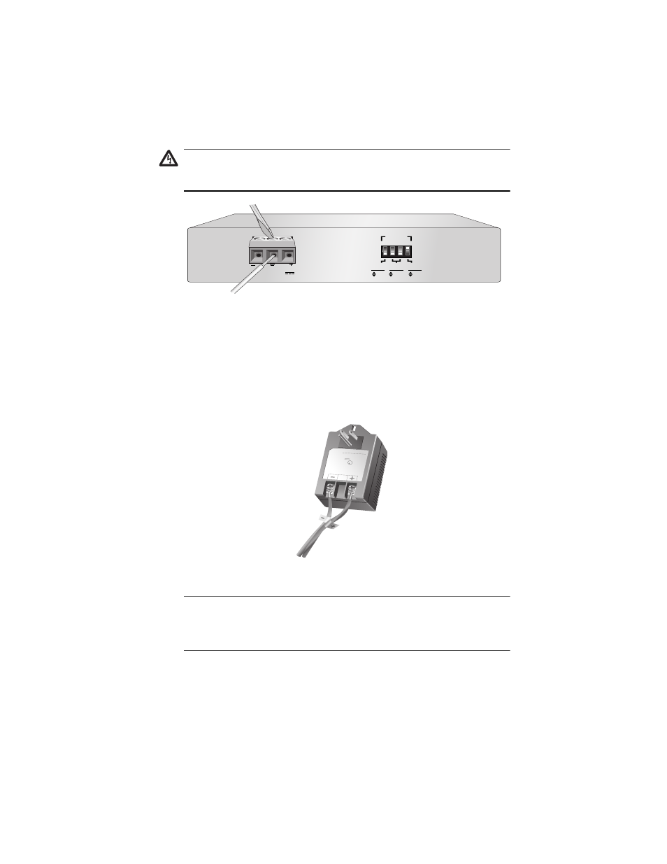
Figure 17 Connecting the Stripped Wire to the 12-50VDC Power Connector
6.
Connect the negative feed wire to the terminal block marked (-).
7.
Connect the positive feed wire to the terminal block marked (+).
8.
Connect the other end of the wires to the terminal block on the
AT-PWR237 power adapter or approved SELV power source per IEC
60950 (rated minimum 12-50VDC, 0.5A).
Figure 18 Connecting the Stripped Wires to the Optional AT-PWR237 Power Adapter
Note
The optional AT-PWR237 module does not have a terminal for the
ground feed wire. Connect the ground wire from the bridging converter
to the nearest chassis ground.
9.
Secure the power supply cable in the Restricted Access Area using
multiple cable ties to minimize the chance of the connections being
disturbed by casual contact with the wiring.
12-50VDC
2
1
3
4
1
2
2 2
PORT
10
100
HALF
FULL
OFF
ON
DUPLEX
MODE
AUTO
NEG
SPEED
(Mbps)
APS
POWER SUPPL
Y
MODEL NO.: AD-740-1150
/SCG
INPUT: 115V~, 50-60Hz, 1
A.
OUTPUT: 15V , 2
.6A
CAUTION:
F o r I ndoor Use Only.
ADVANCED POWER SOLUTIONS
T E L : ( 9 2 5 ) 4
5 6 - 9 8 9 0
Use only with duple
x receptacle ha
ving center scre
w
Secure unit in place b
y receptacle co
ver screw
Cable type "DP-1" or "DP-2"
U
L
E142017
LISTED
I.T.E.POWER
SUPPLY
4Z38
REV-00
JX-01
RT