Allied Telesis AT-FS238b/2 User Manual
Page 39
AT-FS238a/x and AT-FS238b/x Series Installation Guide
29
3.
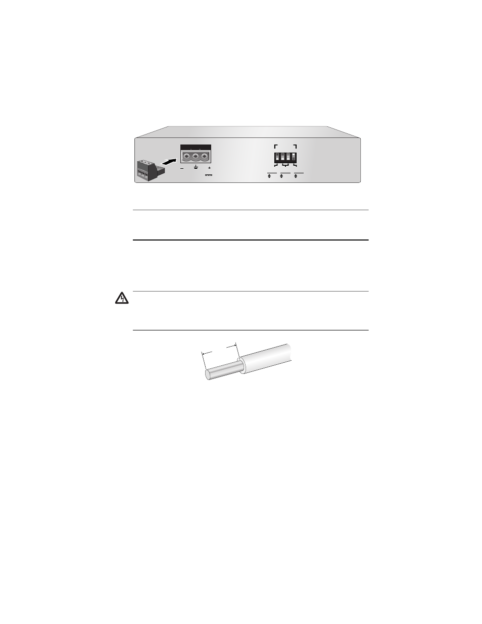
Plug the power connector to the 12-50VDC receptacle connector in the
rear of the converter, as shown in Figure 15.
Figure 15 Connecting the Power Connector to the 12-50VDC Version Model
Note
UL recognized wires of 22-gauge minimum should be provided by the
installer.
4.
With a 22-gauge wire-stripping tool, strip the three wires in the tray cable
coming from the DC input power source to 8mm ± 1mm
(0.31in.± 0.039in.), as shown in Figure 16 on page 29.
Warning
Do not strip more than the recommended amount of wire. Stripping
more than the recommended amount can create a safety hazard by
leaving exposed wire on the terminal block after installation.
17
Figure 16 Stripped Wire
5.
Connect the ground wire to the terminal marked with the ground symbol
by inserting the wire into power connector and tightening the connection
with a flathead screwdriver, as shown in Figure 17.
12-50VDC
2
1
3
4
1
2
2 2
PORT
10
100
HALF
FULL
OFF
ON
DUPLEX
MODE
AUTO
NEG
SPEED
(Mbps)
8mm ±1mm
(0.31in. ±0.039 in.)