Location of components – Allied Telesis AT-FS238b/2 User Manual
Page 16
Overview
6
Location of Components
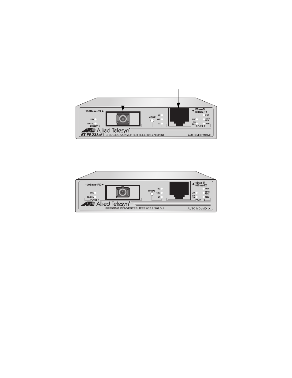
Figure 6 illustrates the front panel of the AT-FS238a/x Series Bridging
Converter.
Figure 6 AT-FS238a/x Series Front Panel (AT-FS238a/1 Model)
Figure 7 illustrates the front panel of the AT-FS238b/x Series Bridging
Converter.
Figure 7 AT-FS238b/x Series Front Panel (AT-FS238b/1 Model)
SINGLE MODE 1310TX/1550RX
Twisted Pair Port
Fiber Optic Port
SINGLE MODE 1550TX/1310RX
AT-FS238b/1
This manual is related to the following products: