Allied Telesis AT-FS238b/2 User Manual
Page 17
AT-FS238a/x and AT-FS238b/x Series Installation Guide
7
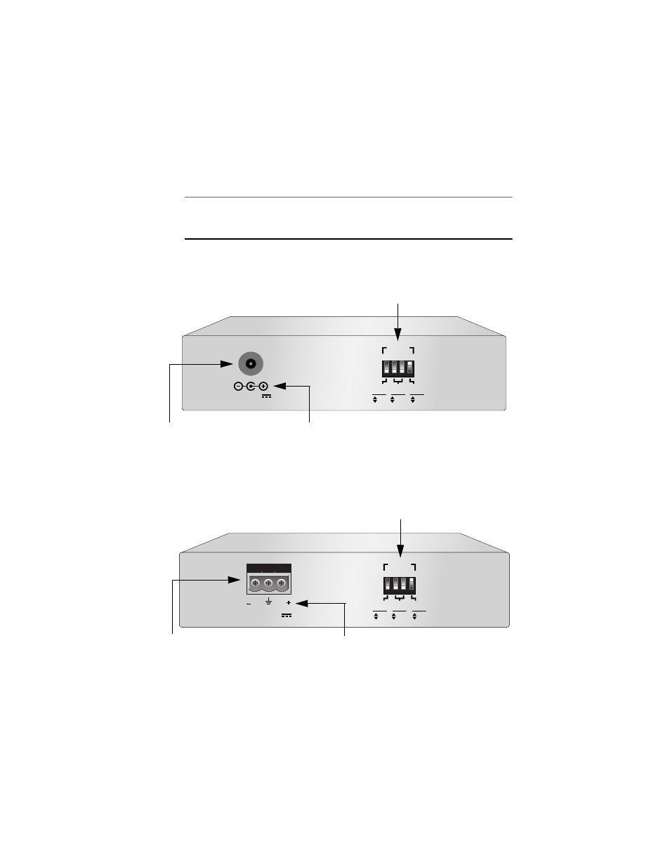
The back panel of the AT-FS238a/x and AT-FS238b/x Series Bridging
Converters features a DC power connector and DIP switches for manually
configuring the ports.
Note
The AT-FS238a/x and AT-FS238b/x Bridging Converters are offered
with two different DC power connectors: 12VDC and 12-50VDC.
Figure 8 illustrates the back panel of the AT-FS238a/x and AT-FS238b/x
Series Bridging Converters with a 12VDC power connector.
Figure 8 Back Panel of the AT-FS238a/x and AT-FS238b/x Series Bridging Converters
(12VDC Power Connector)
Figure 9 illustrates the back panel of the AT-FS238a/x and AT-FS238b/x
Series Bridging Converters with a 12-50VDC, 3-prong power connector.
Figure 9 Back Panel of the AT-FS238a/x and AT-FS238b/x Series Bridging Converters
(12-50VDC, 3-Prong Power Connector)
12 V D C
2
1
3
4
1
2
2 2
PORT
10
100
HALF
FULL
OFF
ON
DUPLEX
MODE
AUTO
NEG
SPEED
(Mbps)
12VDC Receptacle Connector
DC Polarity Symbols
DIP Switches
12-50VDC
2
1
3
4
1
2
2 2
PORT
10
100
HALF
FULL
OFF
ON
DUPLEX
MODE
AUTO
NEG
SPEED
(Mbps)
DIP Switches
12-50VDC 3-Prong Receptacle Connector
DC Polarity Symbols