Caution – HT instruments HT4010 User Manual
Page 34
HT4010
EN - 13
4.3.5 Continuity
test and Diode test
CAUTION
Before taking any in circuit resistance measurement or diode test, remove
power from the circuit to be tested and discharge all the capacitors.
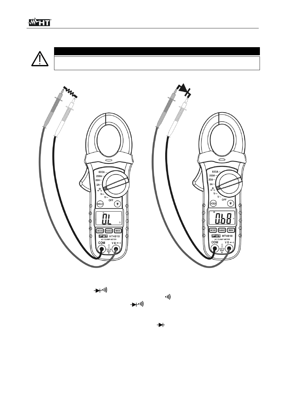
Fig. 6: Taking continuity test and diode test
1. Rotate the switch on
Ω
position
2. Pushing MODE key and select continuity test. The
symbol is shown at display
3. Insert the red test lead plug into V
Ω
jack and the black test lead plug into COM
jack and perform continuity test on the object on test (see Fig. 6 – left side). Buzzer
emits sound if the measured resistance value is less about 150
Ω
4. Pushing MODE key and select diode test. The “
”
symbol is shown at display
5. Connect the red test leads to the anode of diode on test and the black test lead on the
cathode ones (see Fig. 6 – right side). The correspondent threshold voltage of P-N
junction is showed on display
6. Reverse position of test leads to reading inverse polarization voltage