Other products, Fan installation – Hired-Hand Light Traps: Light Trap Adapter Kit User Manual
Page 2
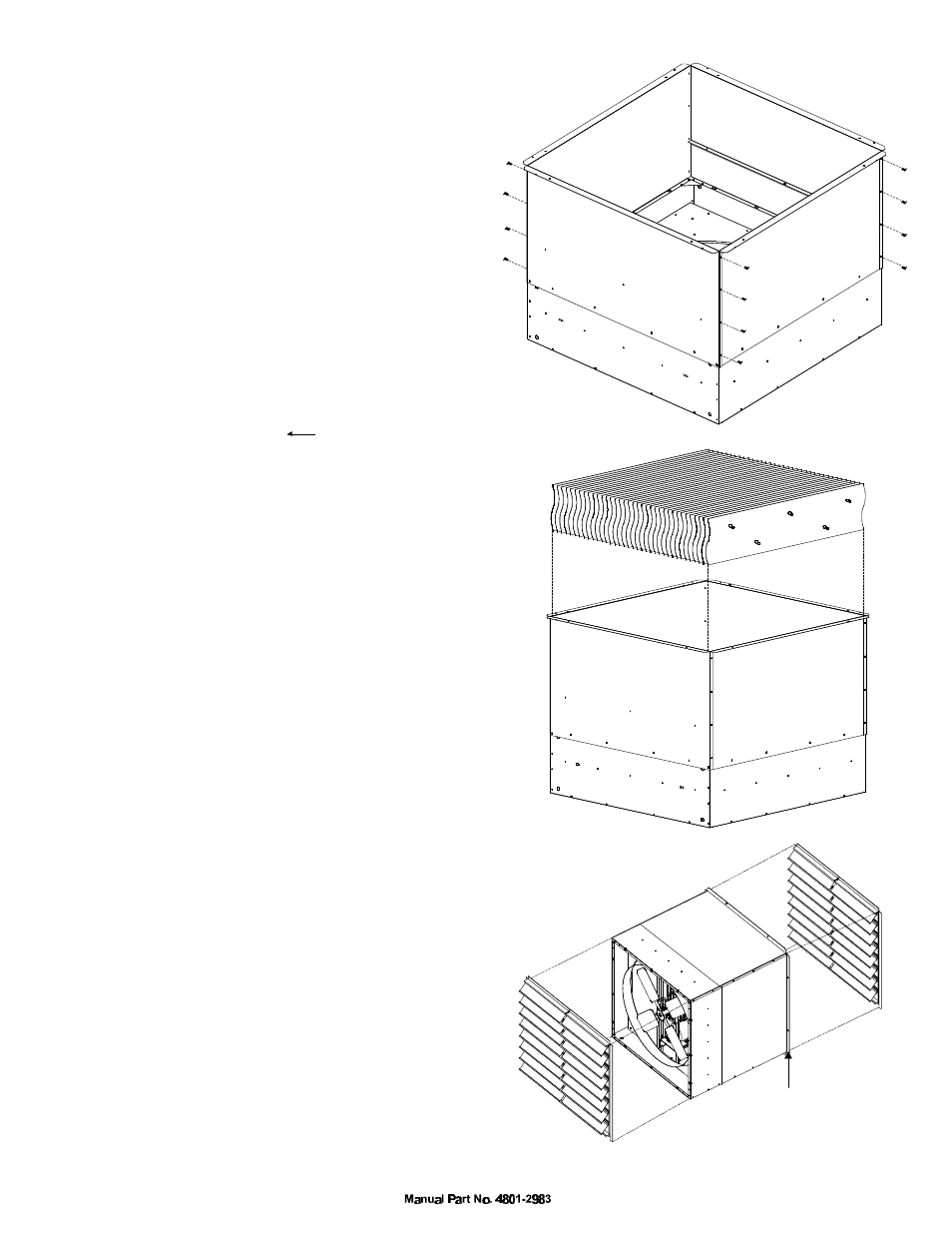
5. Connect sides with 1/4 x 3/8 inch bolts
provided. (See Figure 4)
Fan Installation
1. Cut rough opening in wall. (Minimum dimensions)
a. 48" fans -- 54 3/4" horizontal X 55 3/4" vertical
b. 36" fans -- 42 3/4" horizontal X 43 3/4" vertical
c. 24" fans -- 30 3/4" horizontal X 31 3/4" vertical
2. Place fan through opening blade end first.
3. Slide fan through opening until the flange is against
wall. (See Figure 6).
4. Secure fan to wall with wood screws.
5. Install shutter. Shutter can be either inlet or exhaust.
(Note: Do not replace mesh screen).
6. Connect power to fan.
7. Installation complete.
Other Products
Check out Hired-Hand's new 7 x 44 and
54 x 54 Light Trap Inlets.
HIRED-HAND, INC.
HIRED-HAND, INC. 1733 Co Rd 68 Bremen, AL 35033 Phone 205-287-1000 Fax 205-287-2000
Assemble the Light Trap Extrusions according to
separate instructions which are included with the
Light Trap Extrusions. Insert the assembled Light
Trap Extrusions into the adapter as shown in Figure 5.
Some force may be needed to push the Light Trap
into the adapter. Slide the Light Trap until the
stops are encountered.
Bottom
Side
Motor Pulley Replacement
Light Trap Assembly
And Installation
1. Remove the fan belt. (Insert a screwdriver between the
motor pulley and the belt while rotating the motor pulley).
2. Use an allen wrench to loosen the set screw on the
motor pulley and remove the pulley from the motor shaft.
3. Insert the new pulley onto the motor shaft. Shift the pulley
position on the shaft until the motor pulley is in alignment
with the fan pulley. Use a straightedge held against the fan
pulley to gauge the correct position of the motor pulley.
4. With the motor pulley correctly positioned, tighten the set screw.
Recommended torque of the set screw is 110 In. Lbs. Min.
5. Replace the fan belt according to the following steps.
a. Turn belt with tabs to the inside.
b. Determine the direction of the drive rotation.
c. Align belt directional arrow ( ) with drive rotation.
d. Fit belt over motor pulley.
e. Roll belt onto fan pulley by turning the drive slowly.
Figure 4
Figure 5
Figure 6
Inlet
Exhaust
Fan
Light Trap
Adapter
Shutter
Shutter
This flange is
against wall
f. If belt is too loose or too tight, remove or add links,
respectively, and repeat steps a-e.