Yokogawa EJX430B User Manual
Page 97
<11. General Specifications>
11-6
IM 01C27B01-01EN
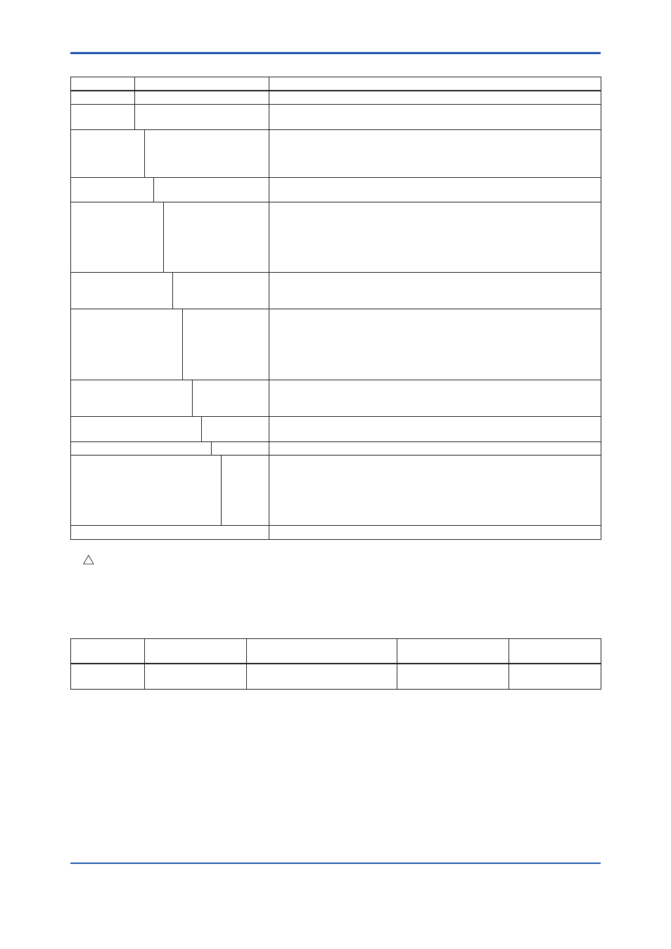
Model EJX310B
Model
Suffix Codes
Description
EJX310B
. . . . . . . . . . . . . . . . . . . . . . Absolute pressure transmitter
Output
signal
-L . . . . . . . . . . . . . . . . . . . .
Wireless communication (ISA100.11a protocol)
Measurement
span (capsule)
L . . . . . . . . . . . . . . . . . . .
M . . . . . . . . . . . . . . . . . .
A. . . . . . . . . . . . . . . . . . .
B. . . . . . . . . . . . . . . . . . .
0.5 to 10 kPa abs (0.15 to 2.95 inHg abs)
1.3 to 130 kPa abs (0.39 to 38 inHg abs)
0.0175 to 3.5 MPa abs (2.5 to 500 psia)
0.08 to 16 MPa abs (12 to 2300 psia)
Wetted parts
material *
1
S. . . . . . . . . . . . . . . . . . Refer to “Wetted Parts Materials” Table 2.
Process
connections
►
0 . . . . . . . . . . . . . . . .
1 . . . . . . . . . . . . . . . .
2 . . . . . . . . . . . . . . . .
3 . . . . . . . . . . . . . . . .
4 . . . . . . . . . . . . . . . .
5 . . . . . . . . . . . . . . . .
without process connector (Rc1/4 female on the cover flanges)
with Rc1/4 female process connector
with Rc1/2 female process connector
with 1/4 NPT female process connector
with 1/2 NPT female process connector
without process connector (1/4 NPT female on the cover flanges)
Bolts and nuts
material
J . . . . . . . . . . . . . .
G. . . . . . . . . . . . . .
C. . . . . . . . . . . . . .
ASTM-B7 carbon steel
316L SST stainless steel
ASTM grade 660 stainless steel
Installation
►
-3 . . . . . . . . . . .
-7 . . . . . . . . . . .
-8 . . . . . . . . . . .
-9 . . . . . . . . . . .
-B . . . . . . . . . . .
-U . . . . . . . . . . .
Vertical piping, right side high pressure, and process connection down side
Vertical piping, left side high pressure, and process connection down side
Horizontal piping and right side high pressure
Horizontal piping and left side high pressure
Bottom Process Connection, left side high pressure
Universal flange
Amplifier housing
7 . . . . . . . . . .
8 . . . . . . . . . .
9 . . . . . . . . . .
Cast aluminum alloy with integral antenna
Cast aluminum alloy with detachable antenna (2 dBi)
*3
Cast aluminum alloy without antenna (N connector)
*2*3
Electrical connection
J . . . . . . . . . No electrical connection, battery-powered type (battery case only; battery
cells not included)
Integral indicator
D. . . . . . .
Digital indicator
Mounting bracket
►
B. . . . .
D. . . . .
G. . . . .
K. . . . .
M . . . .
N. . . . .
304 SST 2-inch pipe mounting, flat type (for horizontal piping)
304 SST 2-inch pipe mounting, L type (for vertical piping)
304 SST 2-inch pipe mounting (for bottom process connection type)
316 SST 2-inch pipe mounting, L type (for vertical piping)
316 SST 2-inch pipe mounting (for bottom process connection type)
None
Optional codes
/ Optional specification
The “►” marks indicate the most typical selection for each specification.
*1:
!
Users must consider the characteristics of selected wetted parts material and influence of process fluids. Specifying inappropriate
materials has the potential to cause serious damage to human body and plant facilities resulted from an unexpected leak of the
corrosive process fluids.
*2:
Order the antenna separately from accessary option.
*3:
Remote antenna cables can be attached. Order separately from accessary option.
Table 2.
Wetted Parts Materials
Wetted parts
material code
Cover flange and
process connector
Capsule
Capsule gasket
Drain/Vent plug
S
#
ASTM CF-8M *
1
Hastelloy C-276 *
2
(Diaphragm)
316L SST (Others)
Teflon-coated 316L SST
316 SST
*1:
Cast version of 316 SST. Equivalent to SCS14A.
*2:
Hastelloy C-276 or ASTM N10276.
The ‘#’marks indicate the construction materials conform to NACE material recommendations per MR01-75. For the use of 316 SST
material, there may be certain limitations for pressure and temperature. Please refer to NACE standards for details.