7 power input 1, 3-pin terminal block, 8 power input 2, din connector, 9 rj-45 rs-232 serial port – IEI Integration UPC-V312-D525 v1.10 User Manual
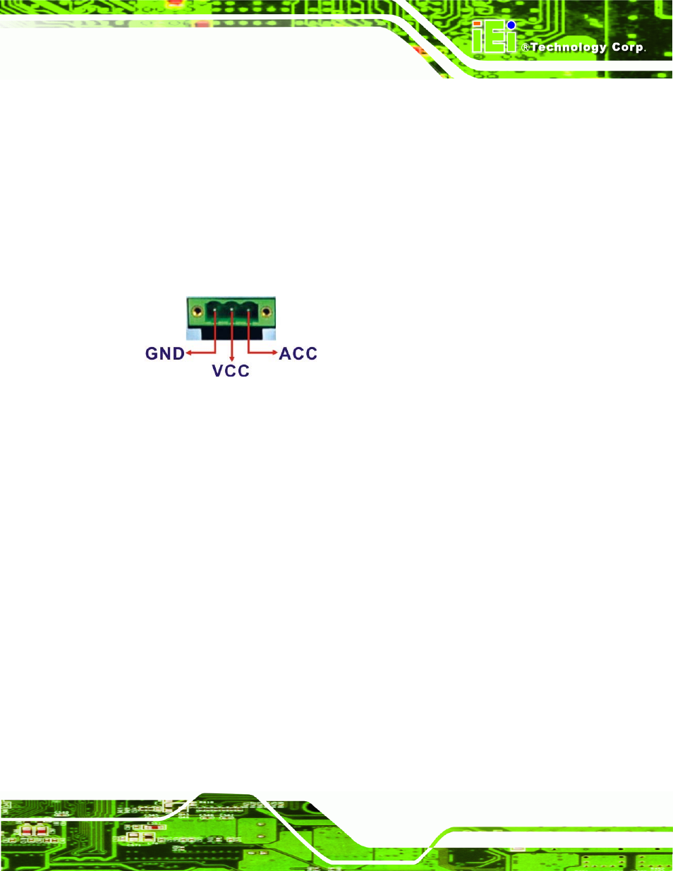
Page 50: Figure 3-25: 3-pin terminal block pinouts
UPC-V312-D525 Panel PC
Page 37
3.7.7 Power Input 1, 3-pin Terminal Block
CN Label:
POWER 1
CN Type:
3-pin terminal block
CN Location:
CN Pinouts:
Connect the leads of a 9V~36V DC power supply into the terminal block. Make sure that
the power and ground wires are attached to the correct sockets of the connector.
Figure 3-25: 3-pin Terminal Block Pinouts
3.7.8 Power Input 2, DIN Connector
CN Label:
POWER 2
CN Type:
DIN connector
CN Location: See Figure 1-4
The power connector connects to the 10.5 V ~ 36 V DC power adapter.
3.7.9 RJ-45 RS-232 Serial Port
CN Label:
RS 232
CN Type:
RJ-45
CN Location:
CN Pinouts:
A RS-232 serial port device can be connected to the RJ-45 RS-232 serial port on the
bottom panel. The pinouts of the RJ-45 RS-232 serial port is shown below.
- UPC-V312-D525 v1.02 (176 pages)
- UPC-12A_GM45 v1.00 (147 pages)
- UPC-12A_GM45 v2.00 (144 pages)
- UPC-12A_GM45 v2.10 (145 pages)
- UPC-V315-NM70 (148 pages)
- UPC-V315-Screw Driver (1 page)
- UPC-V315-QM77 (148 pages)
- S12ASR v1.12 (110 pages)
- S12ASR v3.00 (118 pages)
- PPC-5xxx-9455 v1.00 (198 pages)
- PPC-5xxx-9455 v1.10 (198 pages)
- PPC-WIDS-51xxA-G41 (152 pages)
- PPC-51xxA-H61 (193 pages)
- PPC-5152-D525 v1.02 (183 pages)
- PPC-5152-D525 v2.10 (185 pages)
- PPC-37xxA-N26 v1.00 (203 pages)
- PPC-37xxA-N26 v1.10 (200 pages)
- PPC-37xx-N270 v1.01 (165 pages)
- PPC-37xx-N270 v2.00 (155 pages)
- PPC-37xx-N270 v2.11 (155 pages)
- PPC-37xx-N270 v2.20 (162 pages)
- ACT-457A (67 pages)
- AFL-4 series-N270 v1.05 (165 pages)
- AFL-4 series-N270 v2.10 (166 pages)
- AFL-4 series-N270 v2.11 (168 pages)
- AFL-4 series-N270 v2.20 (168 pages)
- AFL-W19A_W19B_17D_W15A-GM45 v2.10 (138 pages)
- AFL-W19A_W19B_17D_W15A-GM45 v1.06 (138 pages)
- AFL-W19A_W19B_17D_W15A-GM45 v2.20 (151 pages)
- AFL-W15A_17D-GM45 v3.00 (148 pages)
- AFL-15i-HM55 v1.01 (139 pages)
- AFL-19i-HM55 v2.00 (140 pages)
- AFL-15i-HM55 v1.20 (143 pages)
- AFL-W19A_W19B_17D_W15A-N270 v1.06 (125 pages)
- AFL-W19A_W19B_17D_W15A-N270 v2.20 (124 pages)
- AFL-W19A_17D_W15A-N270 v3.00 (126 pages)
- AFL-15A_15AE-N270_UMN_v1.01.pdf (158 pages)
- AFL-15A-N270 v1.03 (159 pages)
- AFL-15A-N270 v2.10 (159 pages)
- AFL-15A-N270 v2.20 (158 pages)
- AFL-xxA-N26 (152 pages)
- AFL-xxA-N270-Series v1.03 (171 pages)
- AFL-xxA-N270-Series v2.00 (171 pages)
- AFL-xxA-N270-Series v2.11 (170 pages)