Table 1-2: led indicators – IEI Integration UPC-V312-D525 v1.10 User Manual
Page 19
UPC-V312-D525 Panel PC
Page 6
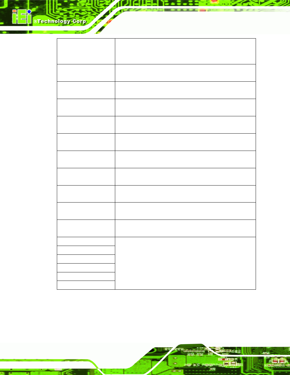
Power 2
Pulsing Orange: Power 2 is the main power and is in standby mode
Solid Orange: Power 2 is the second power and is in standby mode
Solid Blue: Power 2 is providing power to the system
AT/ATX Power Mode
Shows the power mode status. Controlled by the AT/ATX power mode
switch.
CPU Temperature Alert
Blue: the CPU temperature is normal.
Red: the CPU temperature is too high.
Wi-Fi
The Wi-Fi module is enabled or disabled. Controlled by the BIOS (see
Section 4.4.2).
RFID Reader
The optional RFID reader is enabled or disabled.
Controlled by the hot keys (see Section 1.4.6).
Bluetooth
The Bluetooth module is enabled or disabled.
Controlled by the BIOS (see Section 4.4.2).
3G
The 3G module is enabled or disabled.
Controlled by the BIOS (see Section 4.4.2).
GPS
The GPS receiver is enabled or disabled.
Controlled by the BIOS (see Section 4.4.2).
Auto Dimming
The auto dimming function is enabled or disabled. Controlled by the
remote control (see Section 3.9).
Microphone
The microphone is enabled or disabled. Controlled by the BIOS
(Section 4.4.2).
Audio Mute
Light on when the audio is turned off.
Controlled by the hot keys (see Section 1.4.6).
Function
LCD on/off
Volume Down
Volume Up
Brightness Down
Brightness Up
Shows the status of the function key below the LED indicator. Blinks
when the corresponding button is pushed.
Table 1-2: LED Indicators