7 wiring connections, 1 wiring diagram of controller, Fig. 3.z – GeneralAire DS35 Elite Steam User Manual
Page 16: Electrical specifications
16
Elite Steam +03U221903 REV 2.1
WAT E R
I NL E T
DRAIN
VALVE
ST E A M
B OI L E R UNI T
DT
E V F
HL
POWER SUPPLY
(110 VAC 1-PHASE 50-60 HZ
OR
230 VAC 1-PHASE 50-60 HZ)
24 VAC FOR
EXTERNAL
HUMIDISTATS
EXTERNAL DUCT FAN
ALARM
HUMIDISTAT
PROGRAMMING
PORT
NTC AIR PROVING
SENSOR
IN
G
N
D
A
B
A
B
N
1
G
N
D
N
2
N
O
C
N
C
C
N
O
24
Va
c
G
N
D
LCD AND KEY BOARD
E
X
T
FA
N
A
LA
R
M
K
E
Y
HL
N
EVF
EVD
N
F
INT
FA N
E2
E1
L1 L2
ON/OFF
BUTTON
1
2
1
2
4
5
EMBEDDED
BLOWER
EXTERNAL FUSED
DISCONNECT TO BE
INSTALLED (NOT
SUPPLIED) RESPECT
LOCAL CODES
CONNECTED
TO GROUND
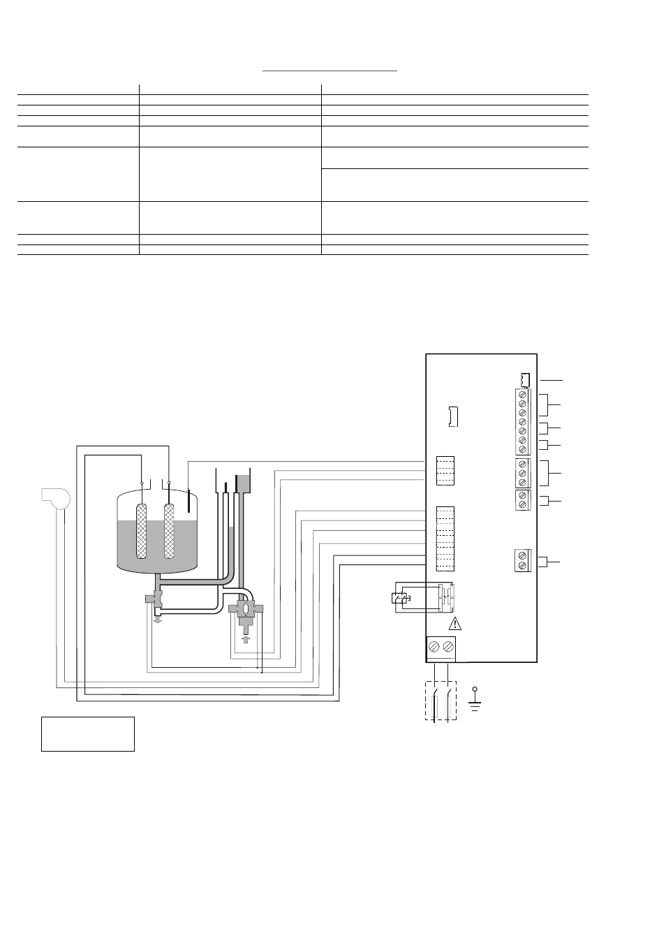
KEY:
EVF = FILL VALVE
DT = DRAIN TEMPERING VALVE
HL = HIGH-LEVEL SENSOR
Fig. 3.z
3.7 Wiring Connections:
3.7.1 Wiring diagram of controller
Terminals
Functions
L1-L2 -GROUND
Power supply and Ground connections
Power supply 110 VAC 1-phase 50-60Hz 1.86kW or 230VAC 1-phase 50-60Hz 4.05kW
KEY
Programming port
Connecting to Programming port or supervisor
-GND-N
2
1
N
NTC air proving sensor
Connection to NTC 2K and 10K to 20°C
AB-AB
Remote enabling input
Imposes an external NO contact ; Rmax= 300 Ohm; Vmax=33 Vdc; Imax=
6mAdc; humidifier enabled = contact closed
IN-GND
Control signal imput
If programmed 0...10V:
Input impedance 10 kohm
If programmed ON-OFF:
Vmax 33Vdc
Imax = 5mA Rmax = 300 Ohm
NC-C-NO
NC alarm contact
Common alarm contact
NO alarm contact
250V; 8Amp max with resistive load; 4 Amp max with inductive load
NO-C
External fan relay
250V; 8Amp max with resistive load; 4 Amp max with inductive load
24-GND
Power for external humidistat
Power supply for external humidistat 24 Vac; 2 Watt
Tab. 3.i
AIR PRESSURE SWITCH
Electrical specifications