5 power wiring, 6 control wiring – GeneralAire DS35 Elite Steam User Manual
Page 14
14
Elite Steam +03U221903 REV 2.1
Fig. 3.r
Fig. 3.q
P R E S S U R E
S W I T C H
H
Fig. 3.u
Fig. 3.v
Fig. 3.t
Fig. 3.o
Fig. 3.p
Fig. 3.s
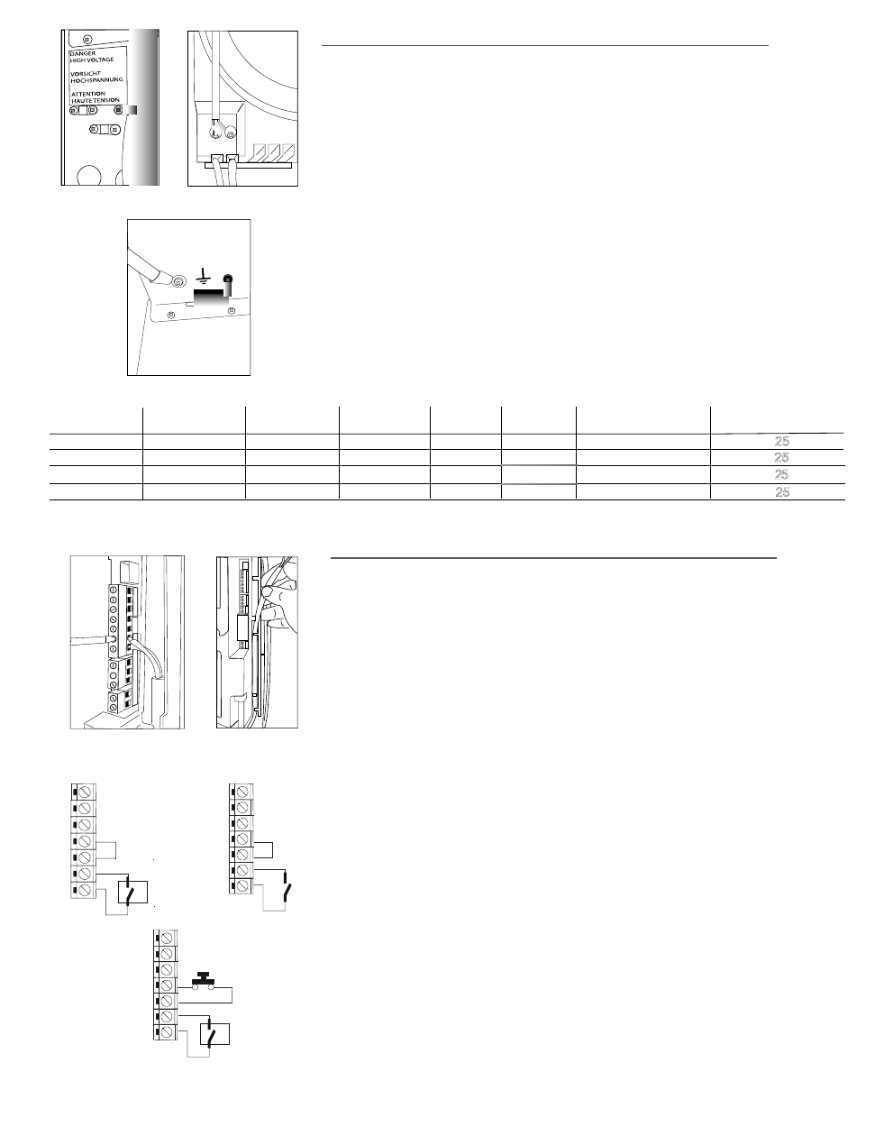
3.5 Power wiring
Check that the power supply voltage to be connected matches the value indicated on the
rating plate inside the electrical panel.
Insert the power and ground connection cables into the electrical panel compartment using
the strain reliefs supplied, and connect to the terminals. An external fused disconnect
must be installed. See Fig. 3.o
All wiring must be in accordance with local, state and national electric codes.
NOTE: to avoid unwanted interference, the power cables should be kept separate from any
control wiring.
NOTE: Tolerance allowed on main voltage = -15% to +10%
Connect power wires to the power terminal block located at the bottom left of the control
module, polarity does not matter. See Fig. 3.p
Connect the ground wire to the unit’s chassis ground, located just behind the power
wiring terminal block. See Fig. 3.q
Model
(single phase)
Steam Ouput
(kg/h)
Steam Ouput
(Ibs/hr)
POWER
(kW)
CURRENT
(A)
EXTERNAL POWER
WIRES
EXTERNAL FUSE (A)
OR BREAKER
DS15
110Vac 56/60Hz
5.5
AWG10
110Vac 56/60Hz
5.5
2.5
1.80
16.40
AWG10
5
230Vac 50/60 hz
230Vac 50/60 hz
12
5.4
3.89 16.95
AWG10
Tab. 3.h
3.6 Control wiring
Elite Steam allows connection of any simple or automatic humidistat, and safety
devices such as high-limit humidistat, air flow proving switch, and remote on/off.
The humidifier is operated by the closing of a mechanical humidistat H, or by the closing
of a voltage-free remote contact CR, or alternatively by a combination of both. The
most common is a combination of a humidistat and pressure switch. The diagrams
in the figures show the connections to be made on the terminal block, in case of :
Fig. 3.u Operation performed by a simple enabling contact;
Fig. 3.t Operation controlled by an external mechanical humidistat;
Fig. 3.v A combination of both humidistat and pressure switch (most common).
Contact AB-AB:
• closed: humidifier enabled to produce steam
(production starts when humidistat closes);
• open: steam production is immediately stopped.
The remote on/off contact is usually a series of external potential-free contacts
that enable the humidifier to produce steam when all of them are closed, indicating the
duct/AHU is ready to accept steam. Connect the 12500 Pressure Switch NO and C
terminals to the AB-AB contacts.
For example,
• fan contact closes when fan is running;
• downstream cooling coil contact closes when coil is off;
• etc.
Contact IN-GND:
• closed: steam production starts if contact AB-AB is closed
• open: steam production is stopped after 5 sec.
AWG10
RS15
DS35
RS35
N2
GND
N1
AB
AB
GND
IN
N2
GND
N1
AB
AB
GND
IN
N2
GND
N1
AB
AB
GND
IN
L1 L2
H
2.5
1.80
16.40
12
5.4
3.89 16.95
5
Power supply