GeneralAire DS35 Elite Steam User Manual
Page 15
15
Elite Steam +03U221903 REV 2.1
Fig. 3.w
Fig. 3.x
3.6.1 Connect the E2 Humidistat for On/Off Operation:
1. Remove the humidistat from the base, squeeze the louvered base at the top and bottom. To remove the humidistat from the wall,
lift up on the humidistat and pivot top away from wall.
2. Before wall mounting, please remove the black foam gasket.
3. Before return air duct mounting, please remove the breakout piece.
4. If return air duct mounting, route wires between humidistat and base.
5. Mount the sensor outside the house. Do not mount on South side of the house or in direct sunlight. Place at least 4 feet away
from any exhaust vent. If in air intake, place 1 foot or closer to outside wall. Place at least 6” higher than possible snow. Do
not route sensor wire near high voltage wires.
6. Connect the GND-IN terminals on the humidifier to the HUM terminals on the E2 Humidistat. Connect the GND-24V terminals
to the ACL-ACN terminals on the E2 Humidistat. see Fig.3.x
3.6.2 Modulating Operation
Connect an external 0...10 Vdc modulating input between terminals IN-GND.
Connect any Safety Switches (high-limit, air flow switch, remote on/off) in series to
terminals AB-AB. If no safety switches are used, then a jumper must be installed between
AB-AB. DO NOT apply any voltage to AB-AB.
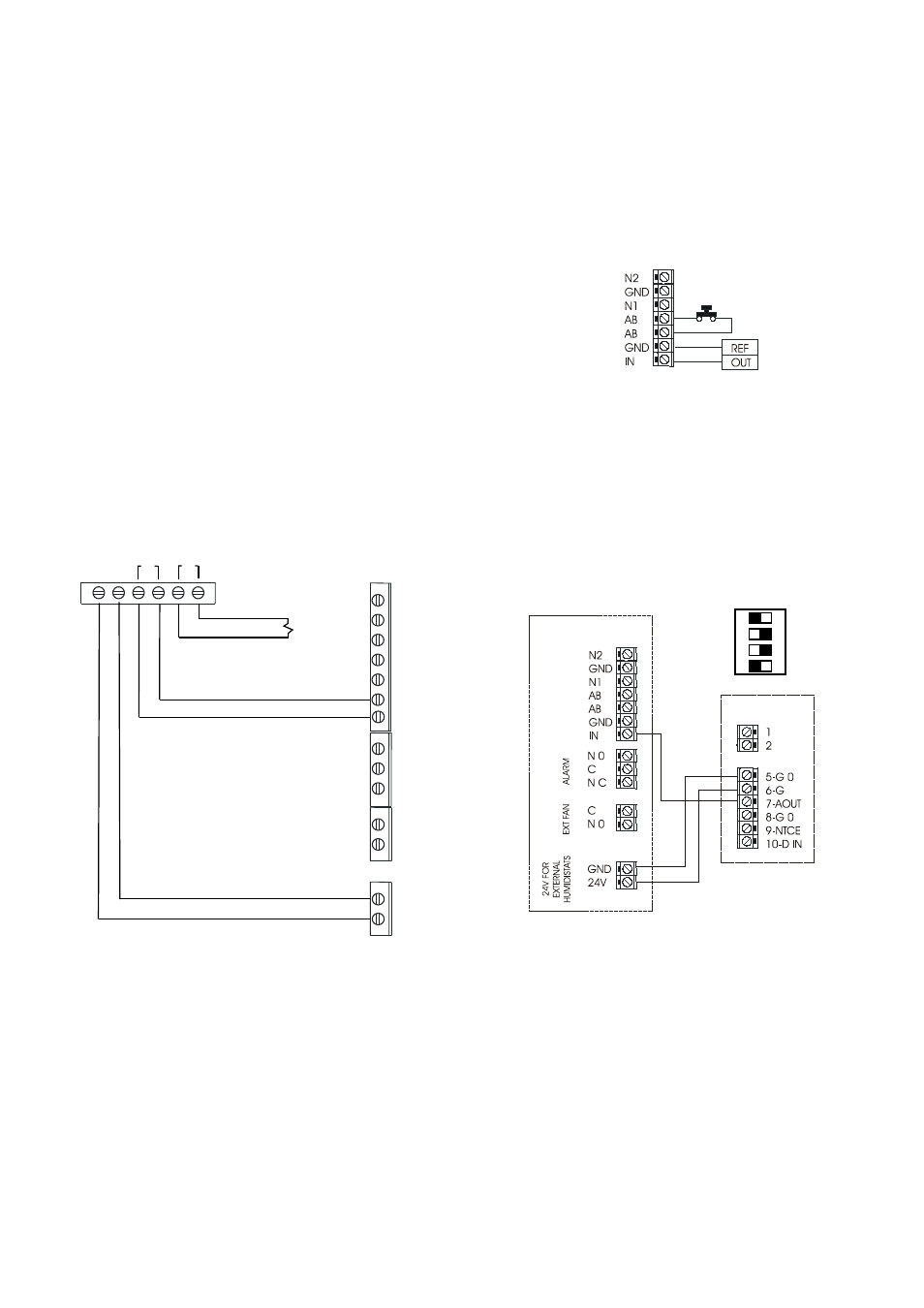
3.6.3 Connect the ADCD humidistat for Modulating Operation
To select signal modulating see Fig 3.y
Connect the power supply to the ADCD G and G O terminals, using the terminal GND and 24V
on the Elite Steam.
Connect an external signal to the ADCD using the terminal IN from the Elite Steam and AOUT in
ADCD.
E2 HUMIDISTAT
ADCD HUMIDISTAT
See the diagram below.
3.6.4 Safety and High Limit Switches
Remove the jumper between terminals AB-AB and connect any simple high-limits, air flow switch, 12500 pressure switch,
and remote contacts in series to terminals AB-AB; otherwise, if no such dry contacts are available, the jumper
must remain in place between terminals AB-AB. DO NOT apply any voltage to AB-AB.
Thread the control wiring through the bottom of the unit, and the strain relief (see photo at top of
previous page), and then up the side of the control module to the top right wiring terminal blocks.
Connect the control wiring to the control wiring terminal blocks found at the top right side of the control
module.
EXTERNAL
REGULATOR
Elite Steam
ON DIP
1 2 3 4
ADCD
DIP SWITCH SETTNGS
FOR HUMIDISTAT ONLY OPERATION
ON
OFF
OFF
ON
P R E S S U R E
S W I T C H
N2
GND
N1
AB
AB
GND
IN
NO
C
NC
C
NO
GND
24V
AC L
AC N
HUM
SNSR
OUTDOOR TEMP. SENSOR
(not used in manual mode)
Fig. 3.y
ADCD