Biamp CI-1 User Manual
Page 7
7
REAR PANEL
Connections from External Devices for Fault Indications
B9)-)";,(;+,6-".()"5(4E,C)C"4/"."-,/=:)"
provides a circuit return that is not directly connected to the CI1 and LSI16 Ground.
These inputs allow the signaling of faults from external devices to the Vocia system
so it may indicate and log faults that could affect emergency operation. These fault
signals are typically derived from contact closures on external devices. For multiple
devices (e.g. Multiple UPS units), fault contacts from each device may be ‘wiredOR’
connected (connected in parallel) to the fault input. UPS fault inputs are typically
derived from UPS units used in the system (e.g. for backup powering of VA8600
units). PSU fault inputs are typically derived from batterybacked power supplies
used to power parts of a Vocia system. EWS PSU fault inputs are derived from
optional emergency microphones (EWSx) to indicate loss of power supply. Ethernet
fault inputs are derived from fault contacts of industrial Ethernet switches used in
critical parts of a Vocia system.
All fault inputs are asserted by connecting the relevant pin to Isolated Ground. The UPS Fault, PSU Fault and EWS PSU Faults must be
;4//);6)C"64"RN>"?9)/"/4/&.--)(6)C"),69)("GA"C,();6";4//);6,4/"4("69(4+=9"5+::&+5"()-,-64("JD.F,D+D"R7RSTL7"B9)"RN>"()3)()/;)"E4:6.=)"
output on the power supply connector may be used for this purpose. The Ethernet Fault input is pulledup internally and does not need an
external pullup.
Connections to LSI16
B9)-)";,(;+,6-".()"5(4E,C)C"4/"34+("JNL"
provided with the CI1 for this purpose. Refer to the LSI16 Operation Manual for the circuit functions of these connectors.
Note that the LSI16 PSU Fault, Protection Fault and Path Fault outputs are connected to the CI1 purely for the purpose of providing
required monitoring resistors (these outputs are not otherwise used by the CI1). If these outputs are required for remote fault indications,
the relevant connections should be removed from the Monitored Outputs connector of the LSI16. As described in the LSI16 Operation
Manual, and external monitoring resistor will be required if these circuits are so used.
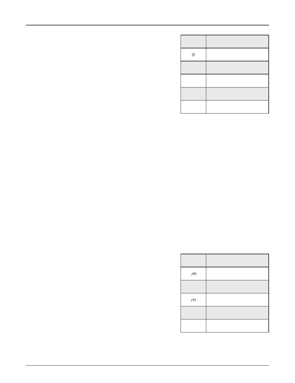
Power Supply Connections
B9)-)";,(;+,6-".()"5(4E,C)C"4/"."-,/=:)"
standards compliance by providing a means of redundant connections.
Each power supply must be capable of 24V DC at 15Watts. The Ground 1 and
Ground 2 connections are internally connected together and to system ground.
The VRef connection may be used as a voltage source for pullups on required fault
inputs. This output is current limited at 100mA.
Loss of power to either power supply input will result in the LSI16 detecting a fault.
If standards compliance is not required for an installation, a single power supply
connection must be paralleled to the two power supply inputs to avoid generating
a fault signal.
Connector
Label
Function
Isolated Ground
U
UPS Fault
P
PSU Fault
W
EWS PSU Fault
E
Ethernet Fault
Connector
Label
Function
Ground 1
1
24 Volts DC Input 1
Ground 2
2
24 Volts DC Input 2
VRef
24 Volts Reference Out