Biamp CI-1 User Manual
Page 6
6
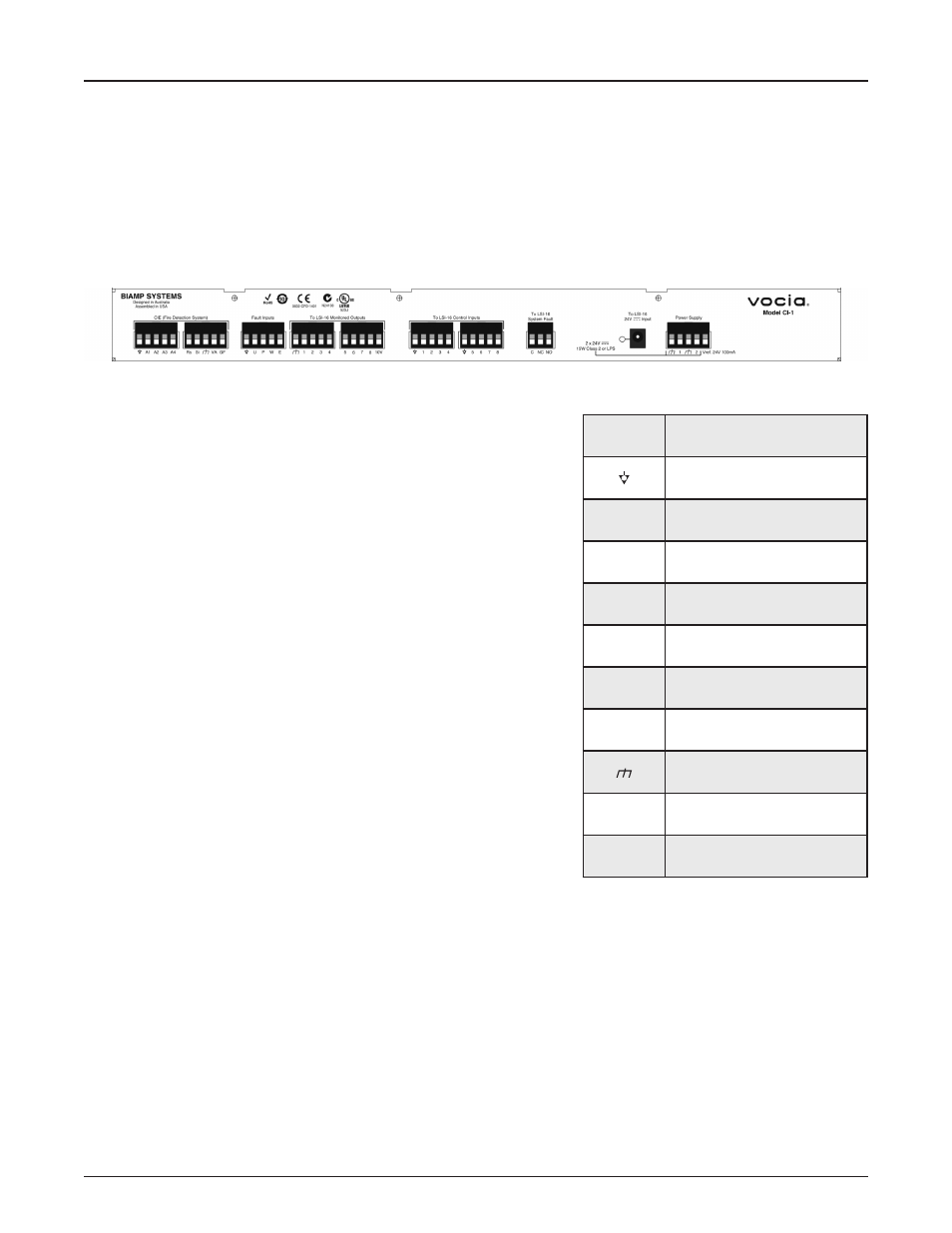
REAR PANEL
There are four main interconnection paths to the rear panel:
!" $4//);6,4/-"64"69)"<()"C)6);6,4/"-A-6)D"J$%KLM
!" Connections from external devices for fault indications
!" Connections to the LSI16
!" Power supply connections
Each of these connection paths has several circuits as detailed below.
Fire Detection System (CIE) Connections
B9)-)";,(;+,6-".()"5(4E,C)C"4/"6?4"
and LSI16 Ground.
#:.(D"%/5+6-"'"69(4+=9"N".()"-,=/.:-"3(4D"69)"<()"C)6);6,4/"-A-6)D7"B9)-)"-,=/.:-"
5:.;)"69)">4;,."-A-6)D",/64")D)(=)/;A"D4C)".;;4(C,/="64"69)";4/<=+(.6,4/"
determined for the input in Vocia software. The Alarm Reset Input cancels all active
alarms in the system while the Alarm Silence Input maintains all active alarms but
causes emergency messages to be silenced. The CI1 provides the necessary
terminating resistors for each input. Inputs are asserted by a positive transition
to 1224V with respect to the ‘Isolated Ground’ connection. This transition should
preferably be derived from a dry contact closure to a remote 12V24V source, or
to the CI1 24V Reference Out (see below).
B9)">4,;)"#:.(D"#;6,E)"4+65+6",-"5(4E,C)C"64"-,=/.:"64"69)"<()"C)6);6,4/"-A-6)D"69.6"
the Vocia system has been activated in emergency mode in response to an Alarm
Input. A constant output denotes that an emergency message is playing. A pulsed
output (1.25Hz) indicates that an alarm is active but emergency messages have
been silenced.
B9)"O)/)(.:"P.+:6"Q+65+6",-"5(4E,C)C"64"-,=/.:"64"69)"<()"C)6);6,4/"-A-6)D"69.6"69)()"
is a fault in the Vocia system that could affect delivery of an emergency message.
The Voice Alarm Active and General Fault outputs pull low (to ground) when active.
The outputs are monitored by the LSI16 for opencircuit or shortcircuit to ground or
power supply and for overvoltage on the output pin (>35V DC). If incorrect conditions are detected a Fault is signaled. Output monitoring
3.;,:,6.6)-";4D5:,./;)"?,69"E4,;)")E.;+.6,4/"-6./C.(C-7"P4("D4/,64(,/="5+(54-)-".":4.C"JD.F,D+D"RRSTL"D+-6"G)";4//);6)C"G)6?))/"
each output and a positive voltage source referenced to the LSI16 Ground, at the far end of the connection to the CIE (i.e. at the CIE).
#/"0KU",/C,;.64(";4//);6)C"69(4+=9"."()-,-64("64"."54-,6,E)"E4:6.=)".6"69)"$%K"?,::"-+3<;)".-"."D4/,64(,/=":4.C7"
V46)"69.6"69)"01%&'2"5(4E,C)-"."'W>"-4+(;)".6"69)"X'W>"Q+6Y"6)(D,/.:"4/"69)"01%&'27"Q+65+6-"D.A"G)"5+::)C"+5"64"69,-"-4+(;)M"94?)E)("69)"
total current drawn from the source must not exceed 100mA. If an external voltage source is used for the outputs, it must not exceed 35V
DC and in addition to the output loads, must also be connected to the LSI16 ‘External Supply Overvoltage Monitor’ input (refer to LSI16
User Manual) for monitoring purposes. Due to monitoring constraints, it is not possible to use both the LSI16 internal 10V source and an
external source.
Connector
Label
Function
Isolated Ground
A1
Alarm 1 Input from CIE
A2
Alarm 2 Input from CIE
A3
Alarm 3 Input from CIE
A4
Alarm 4 Input from CIE
Rs
Alarm Reset Input from CIE
Si
Alarm Silence Input from CIE
Ground
VA
Voice Alarm Active Output to CIE
GF
General Fault Output to CIE