Camera interfaces, Control connector, Chapter – ALLIED Vision Technologies Pearleye P-030 LWIR User Manual
Page 25
Camera interfaces
Pearleye Technical Manual V2.3.0
25
Camera interfaces
This chapter gives you information on the control junction, inputs and outputs
and trigger features.
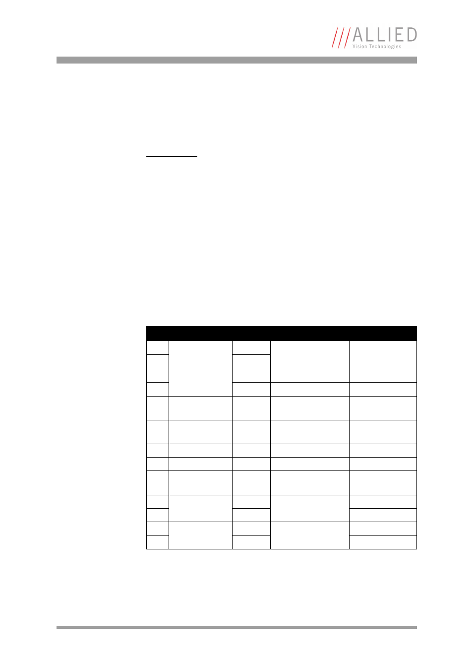
Control connector
Camera I/O connector pin assignment (15-pin
D-sub connector)
This connector is intended for the power supply as well as for controlling the
camera via its serial RS232 interface over a COM port.
Furthermore, some output signals are available, showing the camera state.
www
For accessories like cables see:
Pin
Signal
Direction Level
Description
1
External Power
+12 V DC (-0% / +5%)
Power supply
max. 1.5 A
2
3
External GND
4
5
---
Reserved
(do not connect)
6
---
Reserved
(do not connect)
7
RxD
In
RS232
Camera control
8
TxD
Out
RS232
Camera control
9
---
Reserved
(do not connect)
10
Trigger (Reset)
input
-
optocoupler input
11
+
12
Sensor tempera-
ture too low
-
optocoupler output
13
+
Table 7: Camera I/O connector pin assignment