AAON M1-011 User Manual
Page 16
16
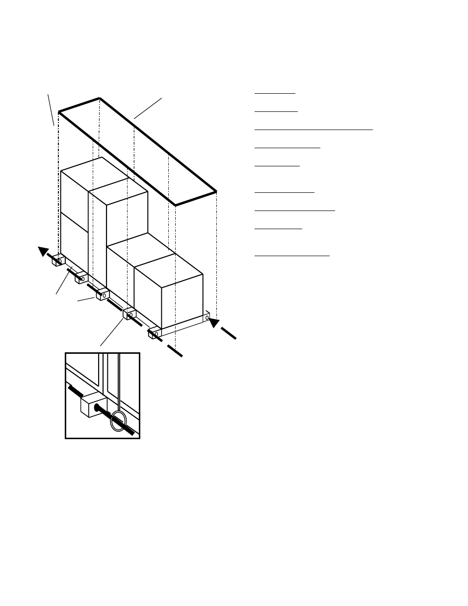
Figure 4.2, Suspended Modular Air Handler
Field Assembly
Although Celebrity1
TM
air handlers are shipped factory
assembled as a standard, they may be ordered
unassembled for certain applications such as for
assembly in existing structures where modules must
be manipulated separately. If the unit was ordered
unassembled, then you will need to connect the
modules in the field.
Modules present may include any or all of the following
depending on the equipment ordered and the
application:
− Fan Module – includes the plenum fan and blower
motor
− Coil Module – contains heating and/or cooling
and/or re-heat coils. May contain electric heat.
− AAONAIRE
Heat Wheel Module – module has
heat wheel installed.
− Air Mixing Module – module where outside air
combines with return air.
− Filter Module – contains slide out filter racks and
filters. May also contain special bag, or cartridge
filters.
− Damper Module – contains motor actuated
horizontal and/or vertical air dampers.
− Power Exhaust Module – includes power exhaust
fan and motor.
− Blank Module – an empty module to be used for
additional controls, parts, or can be used as a
plenum.
− Control Panel Module – an additional module that
contains a control panel when the panel is not
ordered loose, or as part of the fan module.
Locate the configuration schematic in the equipment’s
literature packet. The schematic will have
‘CONFIGURATION’ written in the top left hand corner
followed by the unit model number, and then each
module’s configuration number listed in order.
It is advisable to situate all required modules in the
installation location, and preferably as near as possible
to the order in which they will be connected. Identify
each module by the configuration number on its label.
For example, if a module has a configuration number
of FTF-101-P-A0-00000-00000-0-0, then it is a large
flat filter module (FTF), and should be placed in the
first position (101) of the lower tier i.e. the bottom left.
Although you should have a schematic available, the
configuration numbers have been devised to inform
you of the module assembly without the need for a
schematic. Modules are arranged in order, left to right
with 100 series modules on the first tier, and 200
series modules on the second tier. Module 101 will
always be located on the left end of the bottom tier, or
the bottom left of a right hand assembly, and module
201 will always be located on the left end of the top
tier, or the top left of a right hand assembly. So, it is
possible to identify the exact module arrangement
even without knowing the module type, or having a
configuration schematic.
Suspension
lines
Overhead
Support
Structure
Insert rods
through aligned
holes in base rail
Secure
suspension lines
to rods
Base rail