Prokit's Industries SS-207 User Manual
Page 9
Solders the positive blue lead of sensor to the PC board which link to the blue lead of wire.
Solders the negative red lead of sensor to the PC board which link to the white lead of wire
(3) Solders the two lead of heater to the other side of PC board, bend the leads at right triangle when
soldering to prevent short-circuit
After heating element replaced:
1. Measure the resistance value between pins 2 & 1 or pins 3 & 1 or pin 3 & 2. If it is not ∞, the heating
element or sensor touching the housing ground, it must be eliminated; otherwise will damage the PCB
2. Measure the resistance value between all leads' to confirm that the leads are not twisted and that the
grounding spring is properly connected.
Soldering iron cord damaged
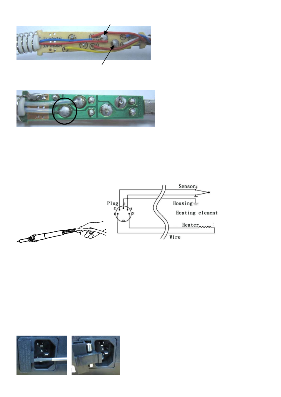
Testing the soldering iron cord
Heating element lead diagram
Check the resistance between the pin of the plug and the wire on the terminal.
Pin 1: Red Pin 2: Blue Pin 3: yellow Pin 4: White Pin 5: Red
The value should be <2Ω. If it is more than 2Ω or ∞, the soldering iron need to be replaced.
Fuse replacement
When fuse is blown, replace with the same type of fuse. (refer to below picture)
1.
Unplug the power cord from the power receptacle.
2. The fuse holder is located under the AC power receptacle, use the slotted (–) screwdriver to loosen
the fuse holder
3.
Replace the fuse with new one
4.
Put the fuse holder back in place
8