Figure d-2. example base i/o address switch settin, Figure d-2 – National Instruments PC-DIO-24/PnP User Manual
Page 87
Appendix D
Using Your PC-DIO-24 (Non-PnP) Board
PC-DIO-24/PnP User Manual
D-4
© National Instruments Corporation
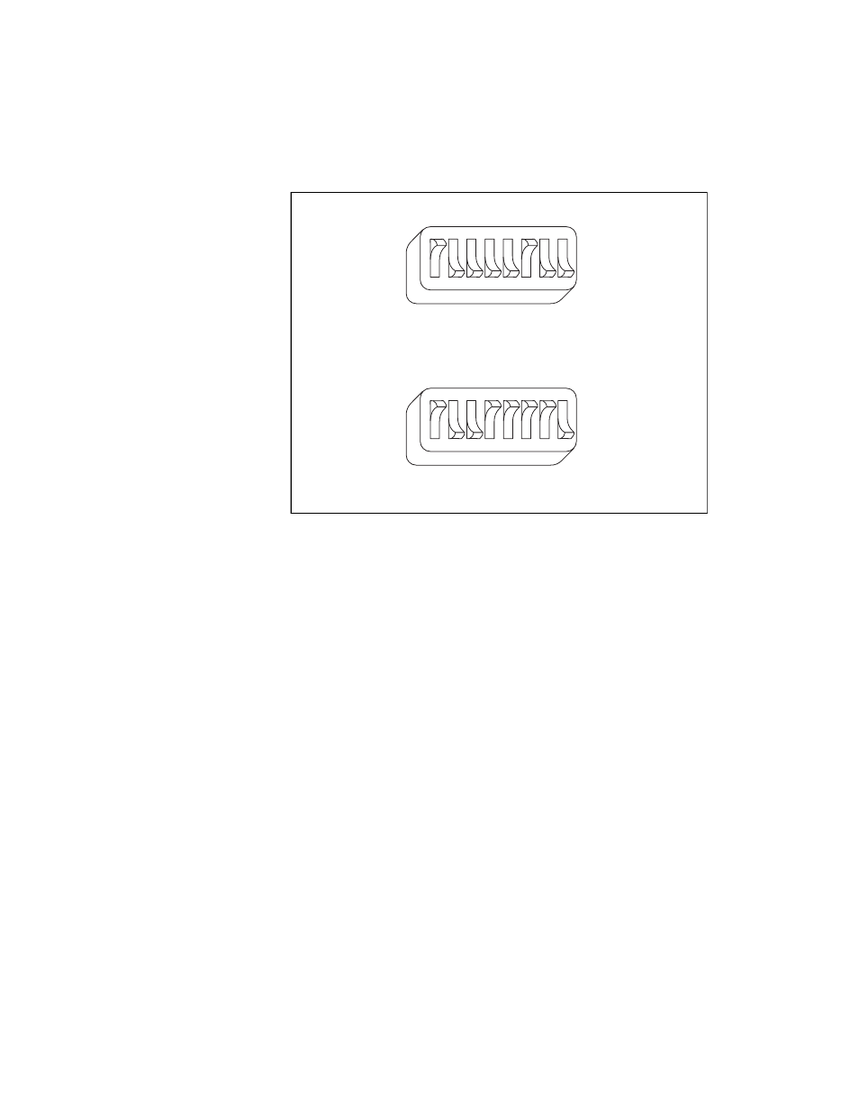
Figure D-2. Example Base I/O Address Switch Settings
Table D-3 shows some examples of switch settings and their
corresponding address ranges.
U9
A9
A8
A7
A6
A5
A4
A3
A2
1
2
3
4
5
6
7
8
b.
Switches Set to Base I/O Address Hex 278
U9
A9
A8
A7
A6
A5
A4
A3
A2
1
2
3
4
5
6
7
8
a.
Switches Set to Base I/O Address Hex 210 (Default Setting)
See also other documents in the category National Instruments Computer Accessories:
- R Series Intelligent DAQ PXI-784xR (14 pages)
- 7344 (66 pages)
- Relay Module SCC-RLY01 (9 pages)
- Compact FieldPoint Mounting Accessories cFP-21xx (10 pages)
- PCI-4451 (115 pages)
- NI 6239 (172 pages)
- SCXI-1190 (54 pages)
- SCXI-1190/1191 (45 pages)
- NI 785xR (74 pages)
- DIO 6533 (125 pages)
- Multisystem eXtension Interface NI PCIe-836x (37 pages)
- GPIB-BUF (40 pages)
- 6527 (47 pages)
- PCI-8336 (43 pages)
- PXI NI PXI-8105 (73 pages)
- 6025E (136 pages)
- NI 78xxR (12 pages)
- PCI-6110E/6111E (113 pages)
- NI 6115/6120 (127 pages)
- 1128 (97 pages)
- 800 Series (104 pages)
- NI 6115 (127 pages)
- NI 784xR (74 pages)
- GPIB-100A (43 pages)
- VXI-MIO Series (151 pages)
- Low-Cost Multifunction I/O Board for ISA Lab-PC+ (211 pages)
- PC-LPM-16/PnP (125 pages)
- NI 7831R (71 pages)
- 653X (147 pages)
- VXI/VME 600 (61 pages)
- PXI NI PXI-1052 (70 pages)
- PC-DIO-96 (105 pages)
- NI UES-3880 (14 pages)
- GPIB-COM (56 pages)
- Switch Executive (8 pages)
- AT-MIO-16X (330 pages)
- 7340 PCI (67 pages)
- NI 783xR (73 pages)
- NI CVS-1450 Series (91 pages)
- SCXI-1321 (16 pages)