Setup menus, Video – Panasonic AJ-HD1700PE User Manual
Page 95
95
Setup menus
when the AJ-UC1700G optional board has not been installed.
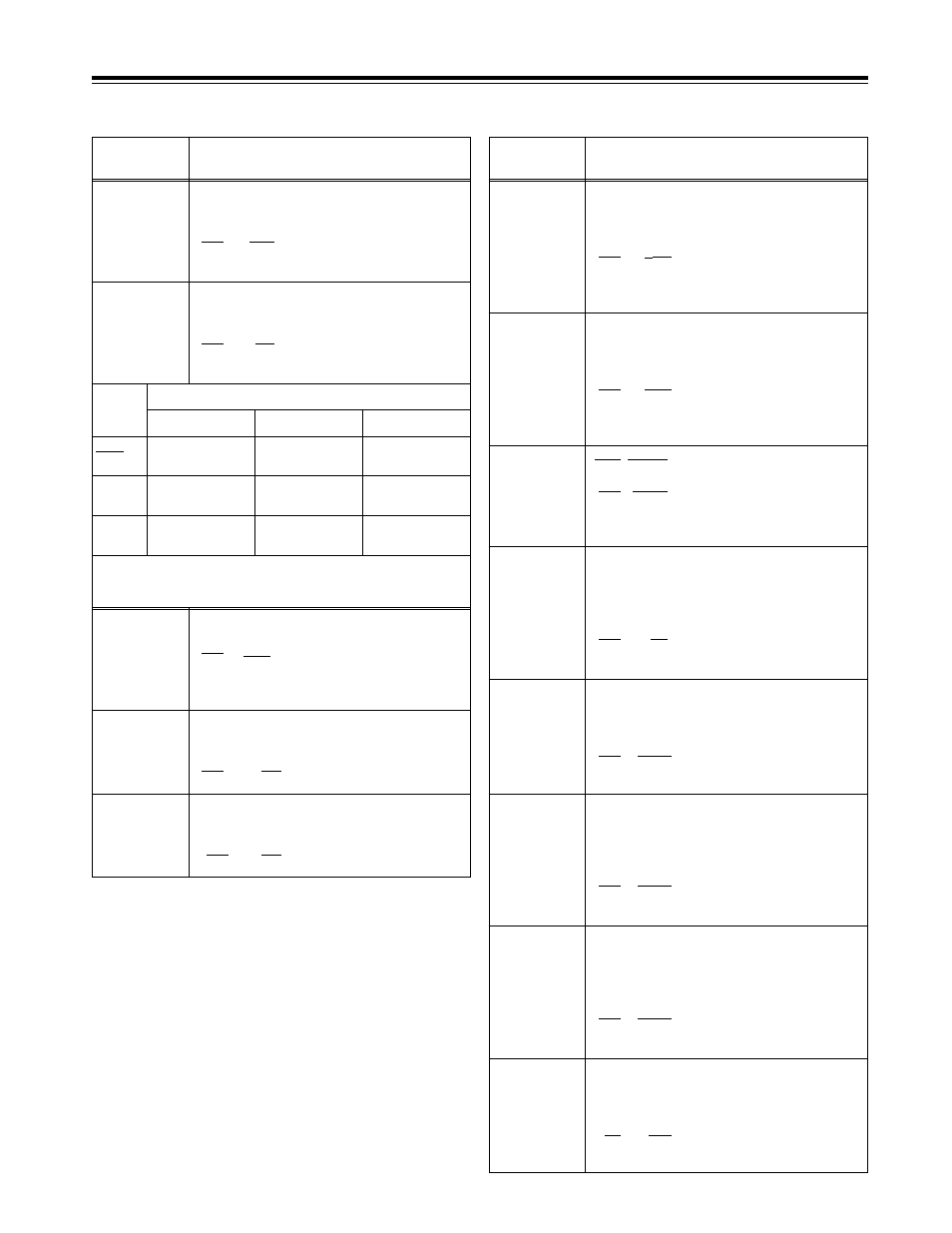
The underlining (__) denotes the factory setting mode.
*UP: With HD output (HD tape playback or up-converted output)
*DW: With SD output (SD tape playback or down-converted output)
(continued)
No./Item
Description of setting
No./Item
Description of setting
637*
2
480i
>
SD_
OUT
For selecting the SD output signal format
during 480i tape (DVCPRO50, DVCPRO, DV or
DVCAM) playback. (See table below.)
0000
480i
0001
480i
0002
480p
636*
2
480i
>
HD_
OUT
For selecting the HD output signal format
during 480i tape (DVCPRO50, DVCPRO, DV or
DVCAM) playback. (See table below.)
0000
1080i
0001
720p
0002
---------
0000
1080i (up-
converted output)
480i
(no conversion)
480i
(no conversion)
720p (up-
converted output)
480i
(no conversion)
480i
(no conversion)
Muted
480p* (up-
converted output)
480i
(no conversion)
0001
0002
HD SDI OUT
SD SDI OUT
Output connectors
VIDEO OUT
638*
1
IN U/C
MODE
For selecting the up-conversion picture frame
when SD SDI input signals are supplied.
0000
FIT_V:
Side panel mode
0001
FIT_H:
Top and bottom cut in vertical
direction
0002
FIT_HV:
Stretch mode
639*
1
I U/C RESP H
For selecting the horizontal frequency band
during the up-conversion of SD SDI input
signals.
0000
STD
0001 NARROW
640*
1
I U/C RESP V
For selecting the vertical frequency band
during the up-conversion of SD SDI input
signals.
0000
STD
0001 NARROW
642*
2
I U/C ENH
V
For accentuating the vertical contours during
up-conversion of SD SDI input signals.
0000
0dB
0001
i
0.7dB
0002
i
1dB
0003
i
1.2dB
0004
i
1.5dB
0005
i
2dB
650
STYLE
0000* CMPNT*:
Level adjustment mode for the
component style
0001
CMPST:
Level adjustment mode for the
composite style
*
The asterisk denotes the factory setting for
AJ-HD1700E.
For adjusting the black level of the HD SDI
output.
50
j
10.0%
:
:
150
0.0%
:
:
250
i
10.0%
“CMPNT” has been selected as the
setup menu item No.650 setting.
656
BK LVL
(HD)*
UP
655
Pr LVL (HD)*
UP
For adjusting the PB level of the HD SDI
output.
(
j
to 0 dB to
i
3 dB)
0000
0.0%
:
:
1000
100.0%
:
:
1413
141.3%
651*
3
HUE STYLE
(SD)*
DW
For selecting the rotational axis of the chroma
phase adjustment.
0000
Pb-Pr:
The axis rotates in a perfect
circle on the SDI (component
style) vectorscope.
0001
U-V:
The axis rotates in a perfect
circle on the analog (composite
style) vectorscope.
653
Y LVL (HD)*
UP
For adjusting the Y level of the HD SDI output.
(
j
to 0 dB to
i
3 dB)
0000
0.0%
:
:
1000
100.0%
:
:
1413
141.3%
654
Pb LVL
(HD)*
UP
For adjusting the PB level of the HD SDI
output.
(
j
to 0 dB to
i
3 dB)
0000
0.0%
:
:
1000
100.0%
:
:
1413
141.3%
“CMPNT” has been selected as the
setup menu item No.650 setting.
“CMPNT” has been selected as the
setup menu item No.650 setting.
“CMPNT” has been selected as the
setup menu item No.650 setting.
display are approximations only.
Hz mode.
*1: This item is not displayed when the 23/24 Hz or 25 Hz (HD or
SD) mode has been selected as the system menu item No.25
(SYSTEM FREQ) setting.
*2: This item is not displayed when the 23/24 Hz, 25 Hz (HD or SD)
or 50 Hz mode has been selected as the system menu item
No.25 (SYSTEM FREQ) setting.
*3: This item is not displayed when the 50 Hz or 25 Hz (HD or SD)
mode has been selected as the system menu item No.25
(SYSTEM FREQ) setting.
*
Setup menu item No.107 and INPUT CHECK do not function,
and the same signal as this signal line is output.
641*
2
I U/C ENH
H
For accentuating the horizontal contours
during up-conversion of SD SDI input signals.
0000
0dB
0001
i
0.7dB
0002
i
1dB
0003
i
1.2dB
0004
i
1.5dB
0005
i
2dB
display are approximations only.