Mdrive34ac plus microstepping connectivity options, P1 p3 – Intelligent Motion Systems MDrive34AC User Manual
Page 2
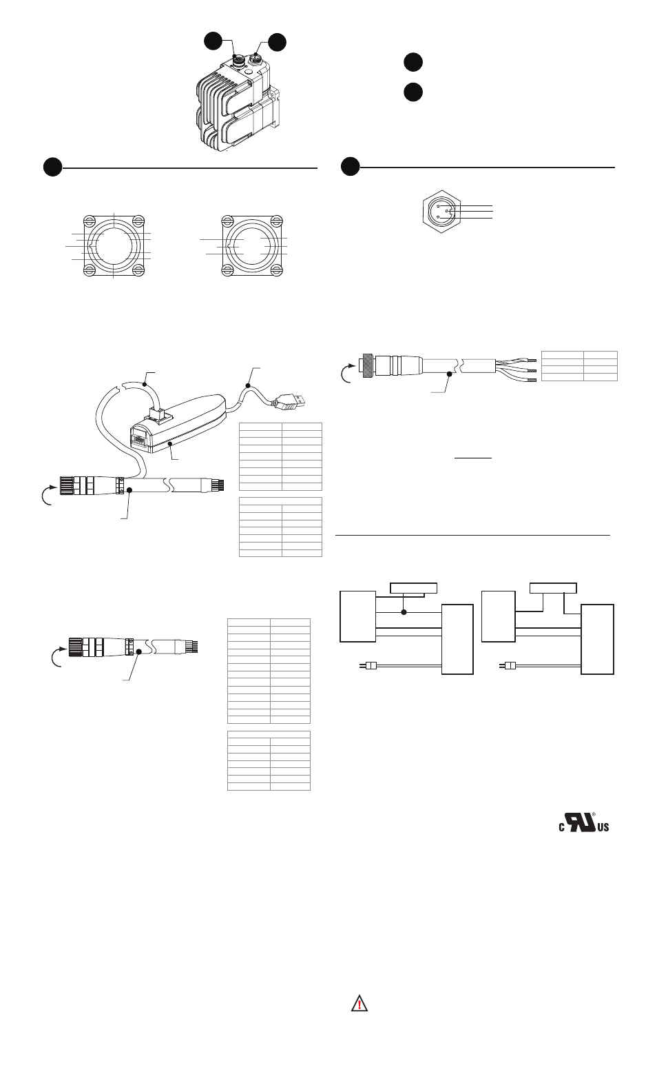
P1
Connector Style
Function
19-pin M23 circular.............. I/O, Communications and
Encoder
3-pin Euro AC...................... Power
MDrive34AC Plus
Microstepping
Connectivity
Options
I/O, Communications & Optional Internal Encoder
19-pin M23 circular connector (male)
P1
P3
P1
P3
Communications Converter p/n: MD-CC301-001
Electrically isolated in-line USB to SPI converter pre-wired with mating connector
to conveniently program and set configuration parameters. A secondary cable
from the mating connector provides interface to power and I/O.
Prototype Development Cordset p/n: MD-CS100/101-000
Speed test and development with pre-wired mating connector.
COM GND
+5VDC
SPI Clock
MISO
CS
Enable
DIR
Step Clock
MOSI
Opto Ref
Shell
IDX-*
CH A-*
CH B+*
CH B-*
CH A+*
IDX+*
Outside: Pins 1--12
2
1
11
10 9 8
7
6
5
4
3
12
Inside: Pins 13--19
19
18
15
14
17 16
13
*No Connect unless populated for the optional internal magnetic
differential encoder
To Controller
To computer
USB port
6.0’ (1.8m)
in-line converter
6.0’ (1.8m)
13.0’ (4.0m)
To MDrivePlus
19-pin M23 (male)
Connector
19-pin M23 (female)
Wire Colors
Function
Violet
Opto Ref.
Red
Enable
Blue
N/C
Black
Comm GND
Green/Yellow Shell
Yellow/Brown Direction
Gray/Brown
Step Clock
Brown
N/C
Optional Internal Encoder
Wire Colors
Function
Gray
IDX+
Red/Blue
CH B+
Green
CH B-
Gray/Pink
CH A+
Brown/Green IDX -
White
CH A-
To Controller
13.0’ (4.0m)
To MDrivePlus
19-pin M23 (male)
Connector
19-pin M23 (female)
Wire Colors
Function
Violet
Opto Ref.
Red
Enable
Blue
N/C
White/Green
MOSI
White/Yellow
CS
White/Gray
+5 VDC
Black
Comm GND
Green/Yellow Shell
Yellow/Brown Direction
Yellow
SPI Clock
Pink
MISO
Gray/Brown
Step Clock
Brown
N/C
Optional Internal Encoder
Wire Colors
Function
Gray
IDX+
Red/Blue
CH B+
Green
CH B-
Gray/Pink
CH A+
Brown/Green IDX -
White
CH A-
Opto
Step
Dir
AC Pwr
Opto
Step
Dir
AC Pwr
I/O Power
GND
Step Out
Dir. Out
GND
Step Out
Dir. Out
Logic Supply
120 or 240 VAC
+
Controller
MDrivePlus
Logic Supply
+
Controller
MDrivePlus
Sinking Configuration
Sourcing Configuration
120 or 240 VAC
Minimum Required Connections
The diagrams below represent the minimum connections required to operate the
MDrivePlus Microstepping.
Copyright © Intelligent Motion Systems, Inc. www.imshome.com
UL Conditions of Acceptability
For full desription of the UL Conditions of Acceptability please visit http://www.
imshome.com/CE_conformity.html
Prototype Development Cordset
p/n (straight connector): MD-CS200-000
p/n (right-angle connector): MD-CS201-000
Pre-wired mating connector interfaces to an MDrive’s 3-pin circular EuroAC con-
nector, with flying leads other end, for quick test/development.
Note that this cable or equivalent Lumberg mating connector/cable must be
used to meet UL conditions of acceptabilty.
Mating Connector Recommendations
The following field-solderable mating connector is recommended for use with the
MDriveAC Plus. Use of this connector meets UL Acceptability requirements.
Lumberg: RKC 30/11
AC Power
3-pin Euro AC connector (male)
P3
Pin 1
Pin 2
Pin 3
Wire Colors
Function
Green/Yellow Earth
Brown
AC Line
Blue
AC Neutral
To MDriveAC Plus
AC Power Connector (male)
12.8’ (4.0m)
To AC Power
3-pin Euro AC (female)
UL Conditions of Acceptability
When used in end-product equipment, the following are
among the considerations to be made:
The temperature tests were conducted with the devices face mounted to
an aluminum heat sink. For devices with the frame designation 34, the
dimensions for the heat sink were 10” x 10” x ¼”. For devices with the frame
designation 42, the dimensions for the heat sink were 12” x 12” x ½”. The
shafts of both frame designations were also provided with aluminum wheels,
approximately 4” in diameter and ¼” thick.
These devices are intended for installation in a Pollution Degree 2 (controlled)
environment. Suitability of the spacings shall be considered in end use ap-
plication.
The enclosure of this device is intended as the final end use enclosure.
These devices do not provide motor overload protection.
These devices have not been subjected to the short circuit test. This test shall
be considered in the end-product investigation.
The following MDriveAC Plus Products are excluded from UL Recognition:
MDriveAC Plus 34 and 42 models with a rear motor shaft exten-
1.
sion, i.e. Control Knob versions
MDriveAC Plus 34 and 42 models with IP-65 sealing.
2.