Warning – Goodman Mfg GKS9 User Manual
Page 27
27
B
OTTOM
R
ETURN
A
IR
O
PENING
[U
PFLOW
M
ODELS
]
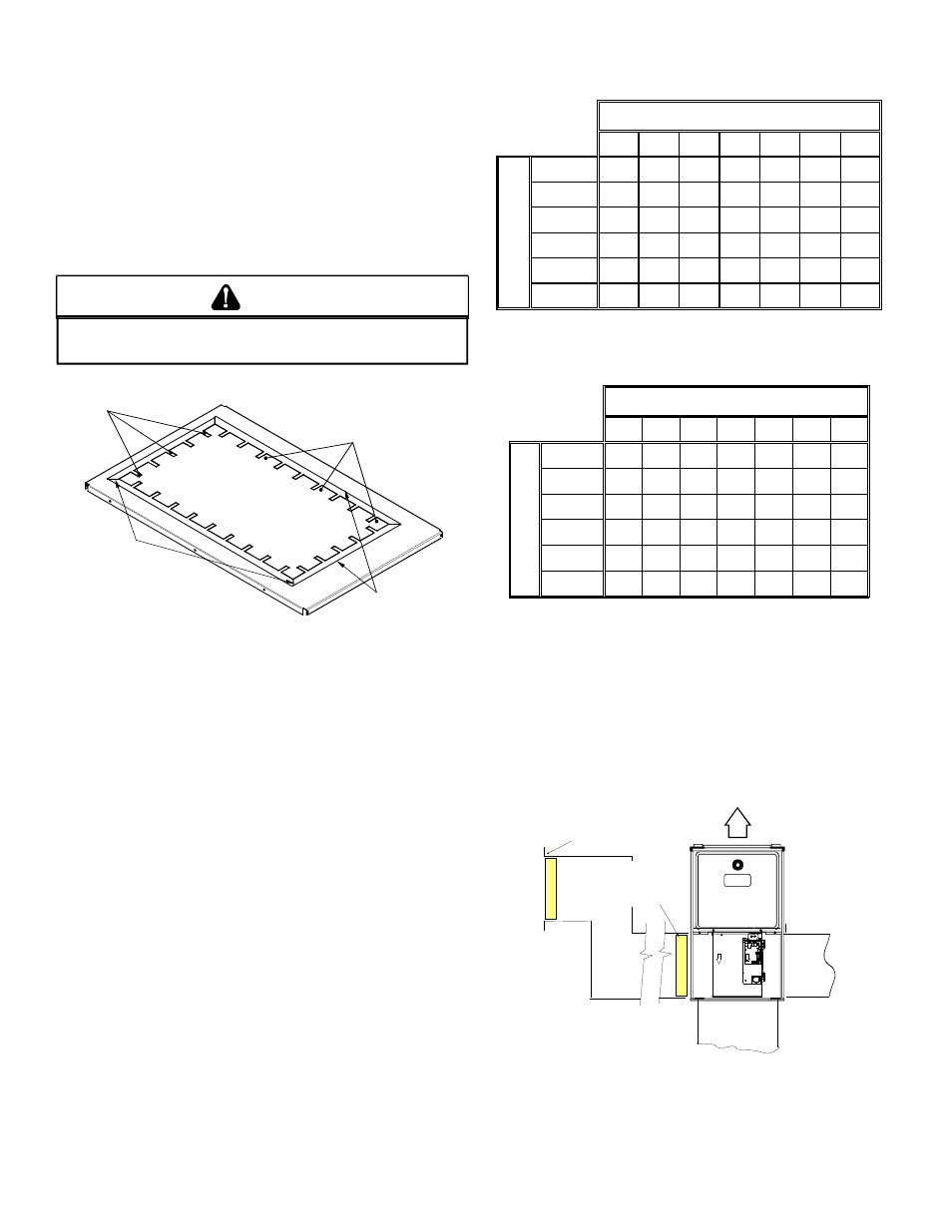
The bottom return air opening on upflow models utilizes a “lance
and cut” method to remove sheet metal from the duct opening in
the base pan. To remove, simply press out the lanced sections by
hand to expose the metal strips retaining the sheet metal over the
duct opening. Using tin snips, cut the metal strips and remove the
sheet metal to free the duct flanges. Using the scribe line along the
duct flange as a guide, unfold the duct flanges around the perim-
eter of the opening using a pair of seamer pliers or seamer tongs.
NOTE: Airflow area will be reduced by approximately 18% if duct
flanges are not unfolded. This could cause performance issues
and noise issues.
E
DGES
OF
SHEET
METAL
HOLES
MAY
BE
SHARP
. U
SE
GLOVES
AS
A
PRECAUTION
WHEN
REMOVING
SHEET
METAL
FROM
DUCT
OPENING
.
WARNING
CUT FOUR CORNERS
AFTER REMOVING SHEET
METAL
CUT USING TIN SNIPS
PRESS OUT BY HAND
SCRIBE LINES OUTLINING
DUCT FLANGES
Duct Flange Cut Outs
When the furnace is used in connection with a cooling unit, the
furnace should be installed in parallel with or on the upstream side
of the cooling unit to avoid condensation in the heating element.
With a parallel flow arrangement, the dampers or other means
used to control the flow of air must be adequate to prevent chilled
air from entering the furnace and, if manually operated, must be
equipped with means to prevent operation of either unit unless the
damper is in the full heat or cool position.
When the furnace is installed without a cooling coil, it is recom-
mended that a removable access panel be provided in the outlet
air duct. This opening shall be accessible when the furnace is
installed and shall be of such a size that the heat exchanger can be
viewed for visual light inspection or such that a sampling probe can
be inserted into the airstream. The access panel must be made to
prevent air leaks when the furnace is in operation.
When the furnace is heating, the temperature of the return air enter-
ing the furnace must be between 55°F and 100°F.
F
ILTERS
- R
EAD
T
HIS
S
ECTION
B
EFORE
I
NSTALLING
T
HE
R
ETURN
A
IR
D
UCTWORK
Filters must be used with this furnace. Discuss filter maintenance
with the building owner. Filters do not ship with this furnace, but
must be provided by the installer. Filters must comply with UL900
or CAN/ULCS111 standards. If the furnace is installed without fil-
ters, the warranty will be voided.
On upflow units, guide dimples locate the side return cutout
locations. Use a straight edge to scribe lines connecting the
dimples. Cut out the opening on these lines. NOTE: An
undersized opening will cause reduced airflow.
Refer to Minimum Filter Area tables to determine filter area require-
ments.
600
800
1000
1200
1400
1600
2000
0453_XA
188*
192
240
288
---
---
---
0703_XA
---
282*
282*
282*
336
---
---
0704_XA
---
---
260*
260*
336
384
---
0904_XA
---
---
376*
376*
376*
384
---
0905_XA
---
---
---
376*
376*
384
480
115_XA
---
---
---
470*
470*
470*
480
Input
__Ai
rf
lo
w
COOLING AIRFLOW REQUIREMENT (CFM)
*Minimum filter area dictated by heating airflow requirement.
Permanent Minimum Filter Area (sq. in)
[Based on a 600 ft/min filter face velocity]
600
800
1000
1200
1400
1600
2000
0453_XA
376*
384
480
576
---
---
---
0703_XA
---
564*
564*
564*
672
---
---
0704_XA
---
---
564*
564*
672
768
---
0904_XA
---
---
752*
752*
752*
768
---
0905_XA
---
---
---
752*
752*
768
800
1155_XA
---
---
---
940*
940*
940*
800
In
p
u
t_
_
A
irflo
w
COOLING AIRFLOW REQUIREMENT (CFM)
*Minimum filter area dictated by heating airflow requirement.
Disposable Minimum Filter area (sq. in)
[Based on 300 ft/min filter face velocity]
U
PRIGHT
I
NSTALLATIONS
Depending on the installation and/or customer preference, differ-
ing filter arrangements can be applied. Filters can be installed in
the central return register or a side panel external filter rack kit
(upflows). As an alternative a media air filter or electronic air cleaner
can be used as the requested filter.
The following figure shows possible filter locations.
FI
LT
E
R
AIR FLOW
CENTRAL
RETURN
GRILLE
FI
L
T
E
R
SIDE RETURN
EXTERNAL FILTER
RACK KIT
(EITHER SIDE)
Possible Upright Upflow
Filter Locations