115 v, 24 v, Warning – Goodman Mfg GKS9 User Manual
Page 23
23
with the furnace must be replaced, it must be replaced with wiring
material having a temperature rating of at least 105°C. Any re-
placement wiring must be copper conductor.
115 V
OLT
L
INE
C
ONNECTIONS
Before proceeding with electrical connections, ensure that the sup-
ply voltage, frequency, and phase correspond to that specified on
the unit rating plate. Power supply to the furnace must be N.E.C.
Class 1, and must comply with all applicable codes. The furnace
must be electrically grounded in accordance with local codes or, in
their absence, with the latest edition of The National Electric Code,
ANSI NFPA 70 and/or The Canadian Electric Code CSA C22.1.
Use a separate fused branch electrical circuit containing properly
sized wire, and fuse or circuit breaker. The fuse or circuit breaker
must be sized in accordance with the maximum overcurrent pro-
tection specified on the unit rating plate. An electrical disconnect
must be provided at the furnace location.
NOTE: Line polarity must be observed when making field
connections.
I
N
UPRIGHT
UPFLOW
INSTALLATIONS
,
THE
DRAIN
TRAP
MUST
BE
MOUNTED
ON
THE
OPPOSITE
SIDE
OF
THE
UNIT
FROM
THE
JUNCTION
BOX
. T
HIS
WILL
REDUCE
THE
RISK
OF
WATER
REACHING
THE
JUNCTION
BOX
IN
THE
EVENT
OF
A
BLOCKED
DRAIN
CONDITION
.
WARNING
Connect hot, neutral, and ground wires as shown in the wiring
diagram located on the unit’s blower door. For direct vent applica-
tions, the cabinet opening to the junction box must be sealed air
tight using either a UL approved bushing such as Heyco Liquid
Tight or by applying a UL approved non-reactive sealant to bush-
ing.
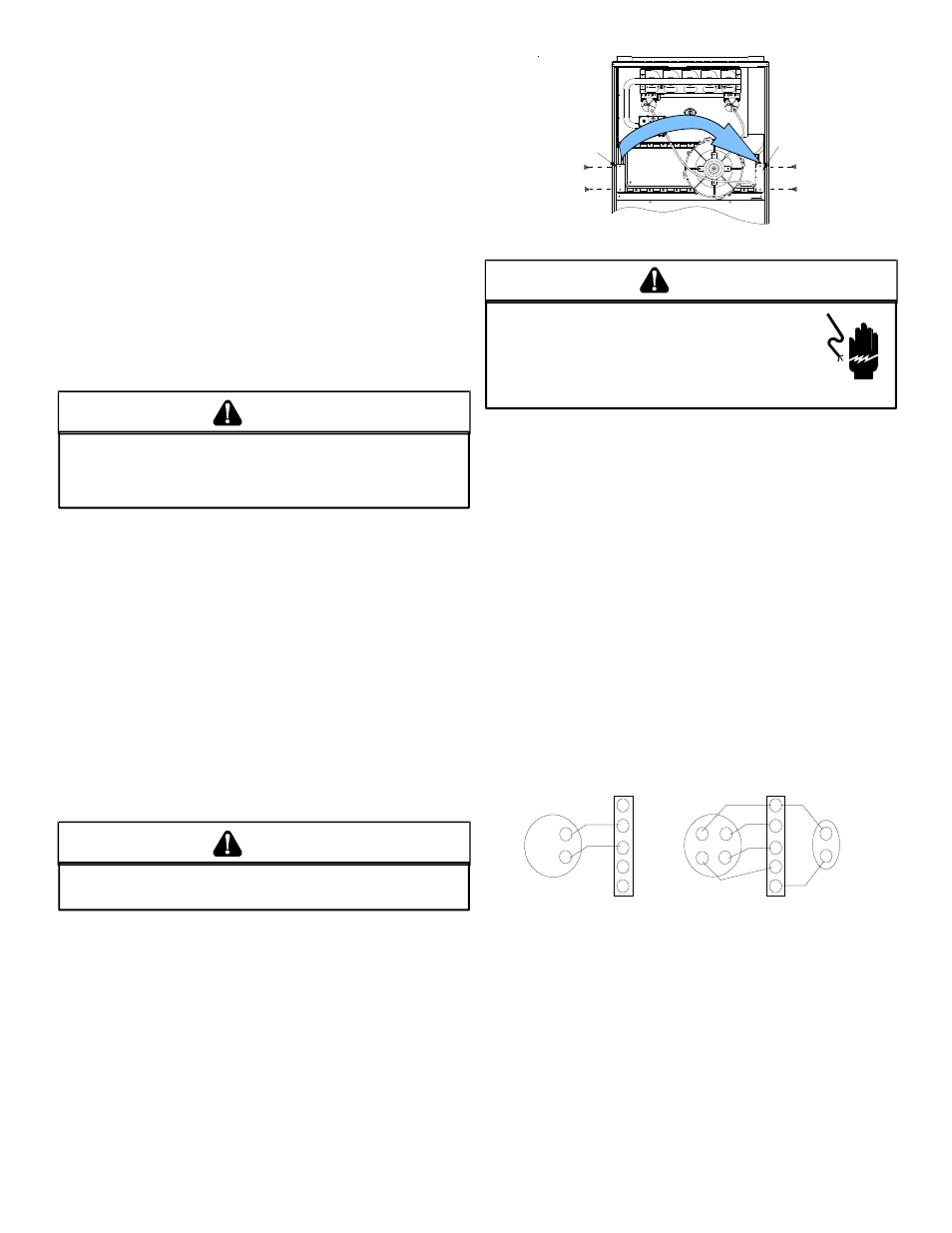
Line polarity must be observed when making field connections.
Line voltage connections can be made through either the right or
left side panel. The furnace is shipped configured for a left side
electrical connection with the junction box located inside the burner
compartment. To make electrical connections through the oppo-
site side of the furnace, the junction box must be relocated to the
other side of the burner compartment prior to making electrical
connections. To relocate the junction box, follow the steps shown
below.
NOTE: Wire routing must not to interfere with circulator blower
operation, filter removal, or routine maintenance.
E
DGES
OF
SHEET
METAL
HOLES
MAY
BE
SHARP
. U
SE
GLOVES
AS
A
PRECAUTION
WHEN
REMOVING
HOLE
PLUGS
.
WARNING
1. Remove the burner compartment door.
2. Remove and save the two screws securing the junction box
to the side panel.
3. Relocate junction box and associated plugs and grommets
to opposite side panel. Secure with screws removed in
step 2.
*
*
*
*
*
*
*
*
*
STANDARD
JUNCTION BOX
LOCATION
ALTERNATE
JUNCTION BOX
LOCATION
Junction Box Relocation
HIGH VOLTAGE!
T
O
AVOID
THE
RISK
OF
INJURY
,
ELECTRICAL
SHOCK
OR
DEATH
,
THE
FURNACE
MUST
BE
ELECTRICALLY
GROUNDED
IN
ACCORDANCE
WITH
LOCAL
CODES
OR
IN
THEIR
ABSENCE
,
WITH
THE
LATEST
EDITION
OF
THE
N
ATIONAL
E
LECTRIC
C
ODE
.
WARNING
To ensure proper unit grounding, the ground wire should run from
the furnace ground screw located inside the furnace junction box
all the way back to the electrical panel. NOTE: Do not use gas
piping as an electrical ground. To confirm proper unit grounding,
turn off the electrical power and perform the following check.
1. Measure resistance between the neutral (white) connection
and one of the burners.
2. Resistance should measure 10 ohms or less.
This furnace is equipped with a blower door interlock switch which
interrupts unit voltage when the blower door is opened for servic-
ing. Do not defeat this switch.
24 V
OLT
T
HERMOSTAT
W
IRING
NOTE: Wire routing must not interfere with circulator blower
operation, filter removal, or routine maintenance.
Low voltage connections can be made through either the right or
left side panel. Thermostat wiring entrance holes are located adja-
cent to the junction box locations in the blower compartment. Wire
routing must not to interfere with circulator blower operation, filter
removal, or routine maintenance. Refer to the following figure for
thermostat connections to the integrated control module terminal
strip.
W
W
W
Y
Y
Y
C
C
R
R
R
G
G
W
Y
C
R
G
HEATING
ROOM
THERMOSTAT
HEATING AND
COOLING ROOM
THERMOSTAT
FURNACE
FURNACE
REMOTE
CONDENSING
UNIT
Thermostat Diagram
This furnace is equipped with a 40 VA transformer to facilitate use
with most cooling equipment. Consult the wiring diagram, located
on the blower compartment door, for further details of 115 Volt and
24 Volt wiring.
XII. GAS SUPPLY AND PIPING
G
ENERAL
The furnace rating plate includes the approved furnace gas input
rating and gas types. The furnace must be equipped to operate on
the type of gas applied. This includes any conversion kits required
for alternate fuels and/or high altitude.