5 external equipment, Figure 2-14 processor unit, inside view – Furuno FR-2115-B User Manual
Page 30
2-11
2.5 External
Equipment
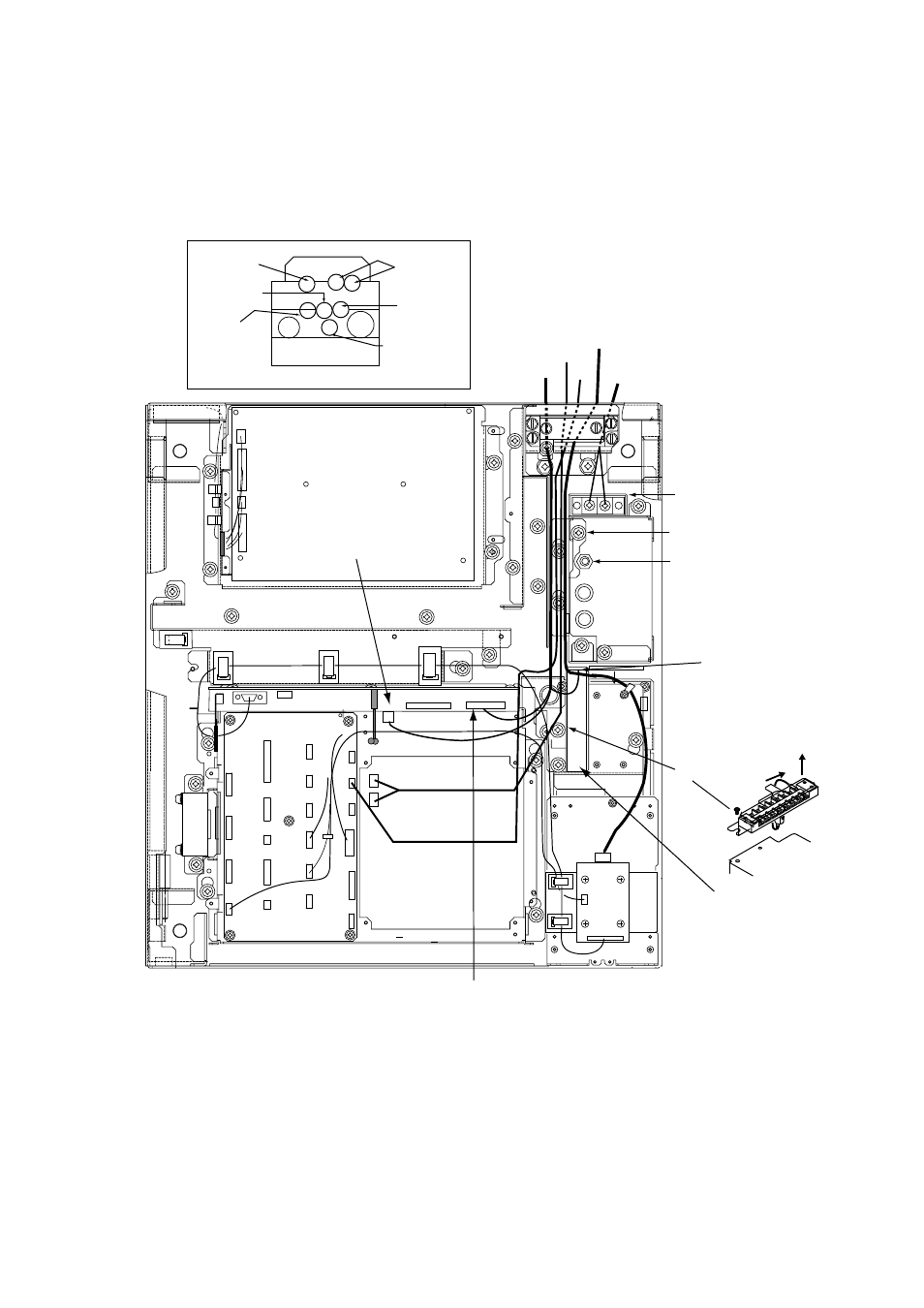
Open the processor unit. Remove the cover from the INT Board. Connect signal, power (ship's
mains and power supply), gyro, log and monitor cables as below. Optional equipment are
connected to the INT Board - see the next page for information.
J463
J444
J443
J442
J446
J467
J448
J445
J449
J465
J455
J466
J454
J450
J456
J453
J451
J458
J457
J452
J462
J5
J4
DJ1
Fasten antenna cable to DJ1
with M3X8 screw (2 pcs., supplied).
INT BOARD 03P9252
GYRO CONVERTER
BOARD 03P9252
POWER switch
(AC spec. only)
Normally ON
TB1
Antenna
PTU BOARD 03P9245
(behind cover)
Ground terminal
Gyro
Log
Monitor
Connect cables
to terminal board
referring to inter-
connection diagram.
M4X8 (2 pcs.)
1
7
3
4
5
2
8
6
2
3
CABLE POSITION IN CABLE CLAMP (front view)
PWR
ANT
Log
Control
unit
Nav equipment
(Gyro, etc.)
Slave display
Monitor
Navigator
MOTHER BOARD 03P9251
Plug in coaxial
cable here.
Ship's mains
Fasten TX-HV line
to #1 terminal.
To fasten;
1. Unfasten screws.
2. Slide terminal forward.
3. Lift terminal to
remove it.
Figure 2-14 Processor unit, inside view