4 control unit – Furuno FR-2115-B User Manual
Page 29
2-10
2.4 Control
Unit
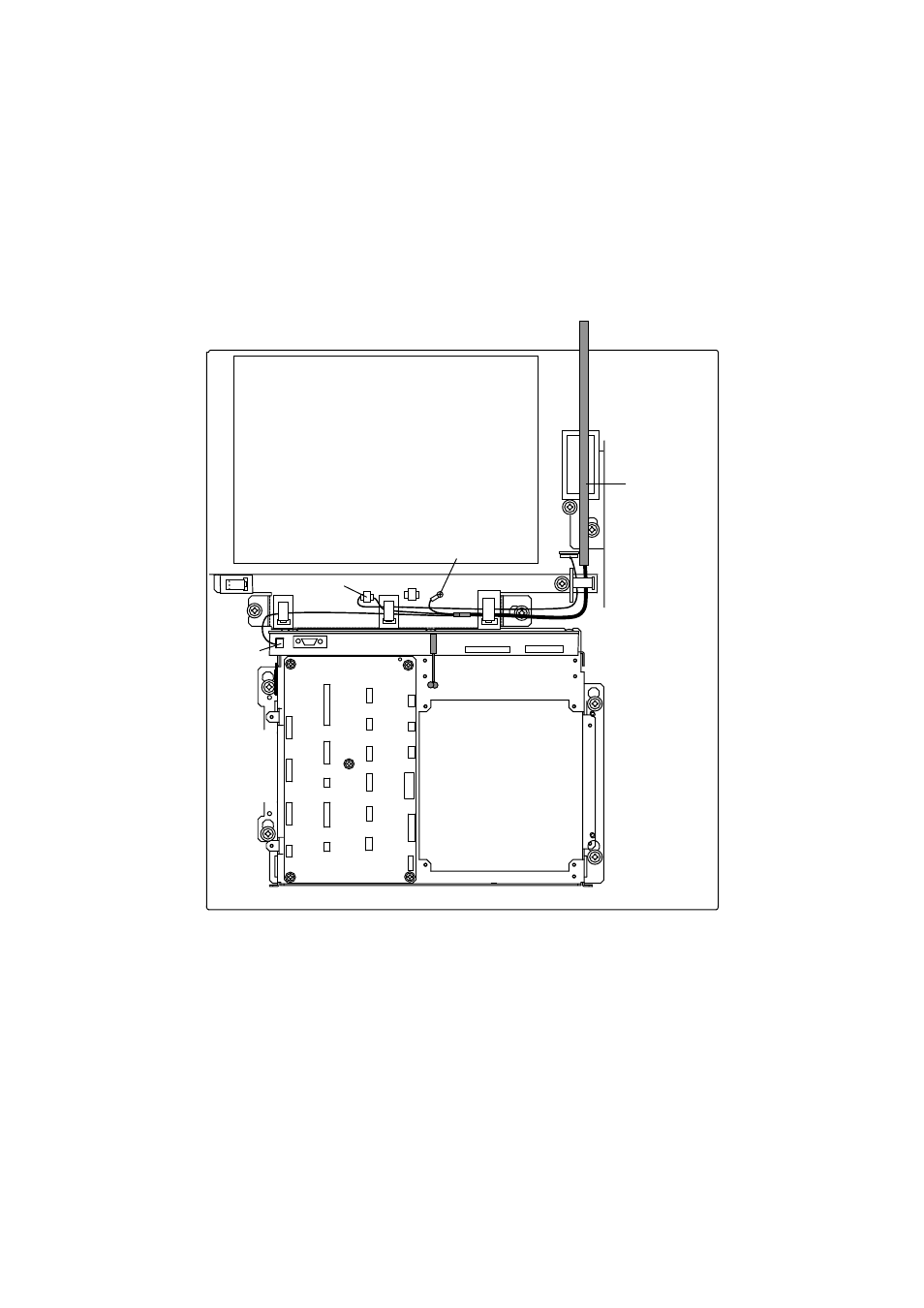
1. Open the processor unit.
2. Lead in the control unit cable assy. (option) from the rear entrance of the processor unit.
3. Inside the processor unit, fasten ground the wire of the cable assembly with an M4 screw on
the chassis.
4. Plug in two connectors of control unit cable to P412 and J583.
MB 03P9251
PTU COVER
INT 03P9252
P412
Control Unit
Cable
J583
Earth Wire
Figure 2-13 Processor unit, inside view
See also other documents in the category Furuno Boating Accessories:
- 2817-D (136 pages)
- 841 MARK-2 (58 pages)
- FAR-2157-BB (111 pages)
- UAIS TRANSPONDER FA-150 (4 pages)
- NAVNET 1763C (260 pages)
- FR-1710 (78 pages)
- FAR-2807 (52 pages)
- MARINERADAR FR-8062 (56 pages)
- 1935 (48 pages)
- FR-7062 (52 pages)
- FR-7252 (48 pages)
- COLOR VIDEO PLOTTER 1943C (251 pages)
- NAVPILOT 520 (73 pages)
- FAR-2167DS (111 pages)
- NAVpilot NAVpilot-500 (73 pages)
- FAR-2827 (135 pages)
- NAVNET 1823C (260 pages)
- FR-2155 (89 pages)
- FA-100 (58 pages)
- NAVNET 1943 (248 pages)
- 1622 (24 pages)
- FR-2115/2125 (79 pages)
- 1942 MARK-2 (52 pages)
- 1942 MARK-2 (46 pages)
- 2137S (123 pages)
- 1832 (62 pages)
- 1832 (64 pages)
- 1832 (63 pages)
- FAR-2167DS-D (111 pages)
- 821 (64 pages)
- FR-8251 (69 pages)
- FR-2135S (82 pages)
- FAR-2127-BB (136 pages)
- NX-700A/B (89 pages)
- MSC.36(63) (1 page)
- IF-1500AIS (12 pages)
- FR-8051 (64 pages)
- FAR-2157 (111 pages)
- FAR-2157 (8 pages)
- 1712 (27 pages)
- UAIS TRANPONDER FA-150 (128 pages)
- FAR-2107(-BB) (312 pages)
- NATVET 1824C (239 pages)
- FAR-2107 (280 pages)
- NAVPILOT 500 (73 pages)