Section 3: installing the fireplace, Installing the fireplace – Heat & Glo Fireplace 8000TVD User Manual
Page 11
11
3
Installing the Fireplace
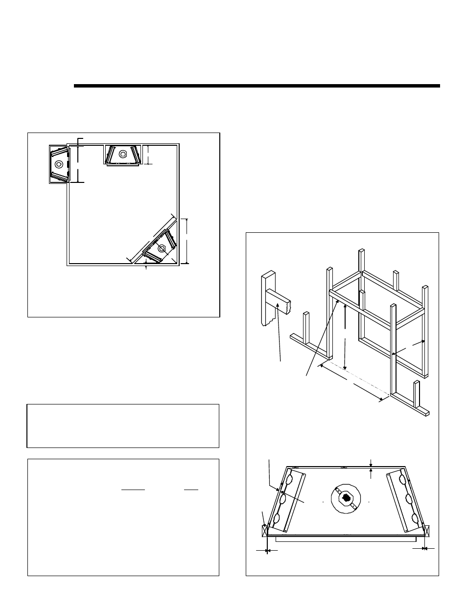
Step 1. Locating the Fireplace
The diagram below shows space and clearance require-
ments for locating a fireplace within a room.
A
B
C
D
E
49”
22”
39 1/2”
56”
79”
Minimum Clearances
from the Fireplace to Combustible Materials
Inches
mm
Glass Front ...................... 36 .................... 914
Floor ................................. 0 ...................... 0
Rear ................................ 1/2 .................... 13
Sides ............................... 1/2 .................... 13
Top ................................. 3 1/2................... 89
Ceiling* ............................ 31 .................... 787
Clearance Requirements
The top, back, and sides of the fireplace are defined by
stand-offs. The minimum clearance to a perpendicular wall
extending past the face of the fireplace is one inch (25
mm). The back of the fireplace may be recessed 21 1/2
inches (546 mm) into combustible construction.
The minimum clearance from the top face of the fireplace
to combustible finishing materials such as drywall, is 1” (25mm).
The distance from the unit to combustible construction
is to be measured from the unit outer wrap surface to
the combustible construction, NOT from the screw
heads that secure the unit together.
A. 49” B. 40 1/2”
C. 22”
Figure 3.
Framing Dimensions
Minimum Clearances from the B-Type Vent Pipe to
Combustible Materials is 1” (25mm) all around the pipe.
Step 2. Framing the Fireplace
Fireplace framing can be built before or after the fireplace is
set in place. Framing should be positioned to accommo-
date wall coverings and fireplace facing material. The dia-
gram below shows framing reference dimensions.
CAUTION: MEASURE FIREPLACE DIMENSIONS AND
VERIFY FRAMING METHODS AND WALL COVERING
DETAILS BEFORE FRAMING.
Framing should be constructed
of 2 X 4 lumber or heavier.
WARNING:
To ensure proper clearances
the front framing header
must be installed on its
narrow edge and to the front
of the frame.
A
B
C
E
1/2“ MIN. (13mm)
D
B
A
C
1” MIN. (25mm)
* The clearance to the ceiling is measured from the top
of the unit, excluding the standoffs (see Figure 13).
Figure 2. Fireplace Dimensions, Locations,
and Space Requirements
1/2” CLEARANCE FROM BACK OF
FIREPLACE TO COMBUSTIBLE
0” CLEARANCE TO
FRAMING MEMBER
0” CLEARANCE
1/2” CLEARANCE FROM BOTH SIDES
OF FIREPLACE TO COMBUSTIBLE
FRAMING
MEMBER