Main frame assembly – HONDA RM752A User Manual
Page 33
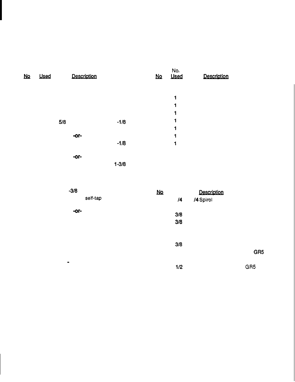
MAIN FRAME ASSEMBLY
Ref
No.
1
1
2
1
3
1
4
2
5
2
6
2
6
2
6
2
6
2
7
2
7
2
8
2
8
2
9
2
10
2
11
4
12
1
Mower frame
Left side
skid
Left side shield
Caster wheel yoke assembly
10-1/4
Caster wheel with sleeve
ID
Flange bearing for
1
bore wheel
3/4
ID Flange bearing for
1
bore wheel
5/8 ID
Flange bearing for
bore wheel
-or-
3/4 ID
Flange bearing with groove
for
1
bore polyethylene wheel
Straight
1/4
grease
fitting
(for steel wheel)
Straight
1/8
pipe thread grease
fitting
(for polyethylene wheel)
1/2
x
3/4
x
3-3/8
Sleeve
17 GA
Wall x
5/8
x
3-3/8
sleeve
Caster arm assembly
1/4 28
Tapered thread grease
fitting
Caster arm adjustment bracket
Access
hole cover assembly
-or-
Ref
13
14
15
16
17
18
19
20
Ref
29
30
31
32
33
34
35
36
37
38
39
40
1
. .
Discharge chute (for use on
mowers with CW blade rotation)
Side shield baffle
Right side shield
Right side
skid
Front corner baffle
Complete English decal set
English safety decal set
French safety decal set
HARDWARE
1
x
1-1
pin
3/8
NC x
3/4
Carriage bolt
NC x
1
Hex head cap screw
GR5
Standard lockwasher
3/8
NC Hex nut, plated
3/8
NC Flanged hex locknut
NC Wing nut
1/2
NC x
1-1/2
Hex head cap screw
1/2
NC
x
1-3/4
Carriage
bolt
HT
NC x 5 Hex head cap screw
1/2
NC Flanged hex locknut
3/4
SAE Flat washer
F-7756 (1
0-89)
31