HONDA RM752A User Manual
Page 16
Attaching Mower to Tractor
Tractor Stability (figure
6)
A minimum
20%
of tractor and equipment
weight must be
on
tractor front wheels with
mower
in
transport position. Without this
weight, tractor could
tip over causing personal
injury
or
death. The weight may
be
attained with
front wheel weights, ballast
in tires or front
tractor weights. When attaining the minimum
20%
weight
on
the front wheels, you must
not
exceed the Roil Over Protection Structure
(ROPS) weight certification. Weigh the tractor
and equipment. DO NOT GUESS
OR
ESTIMATE!
A
Figure 6. Tractor Stability
Place mower on a level surface. Back tractor up to
mower and attach lower 3-paint lift arms to mower
hitch pins. Secure with Kiik pins.
Make sure tractor PTO spring-activated locking
collar slides freely
and
is seated
firmly
in
mower
driveline spline groove.
Attach mower drive shaft to tractor PTO.
Attach tractor top link to mower top link pivots.
Adjust tractor top link
to raise mower front end at
least
making sure the back end clears the
ground and top pivot links have free travel when
raised.
Cutting Height Adjustment
(figure
7 )
Place tractor and mower on a level surface. Check
tractor tire pressure to make sure it
is
correct and
equal.
The adjustments given are
to
provide you with a
starting point. Adjustments are approximate and
may vary due
to
machine wear. You may desire
to
fine tune them
for
your situation.
IMPORTANT NOTICE
Avoid very low cutting heights. Striking the
ground with blades gives one of the most
damaging shock loads a mower can encounter.
Severe shock loads can damage the mower
drive and/or the tractor transmission.
Mower cutting height is raised, lowered, and main-
tained with tractor hydraulics and top link adjust-
ment, check chains and caster arms.
Place a straightedge along mower deck edge from
front to rear (refer
to figure
8).
Measure from each
front corner
to
the ground to be sure mower
is level.
Use tractor 3-point arm adjustment as required.
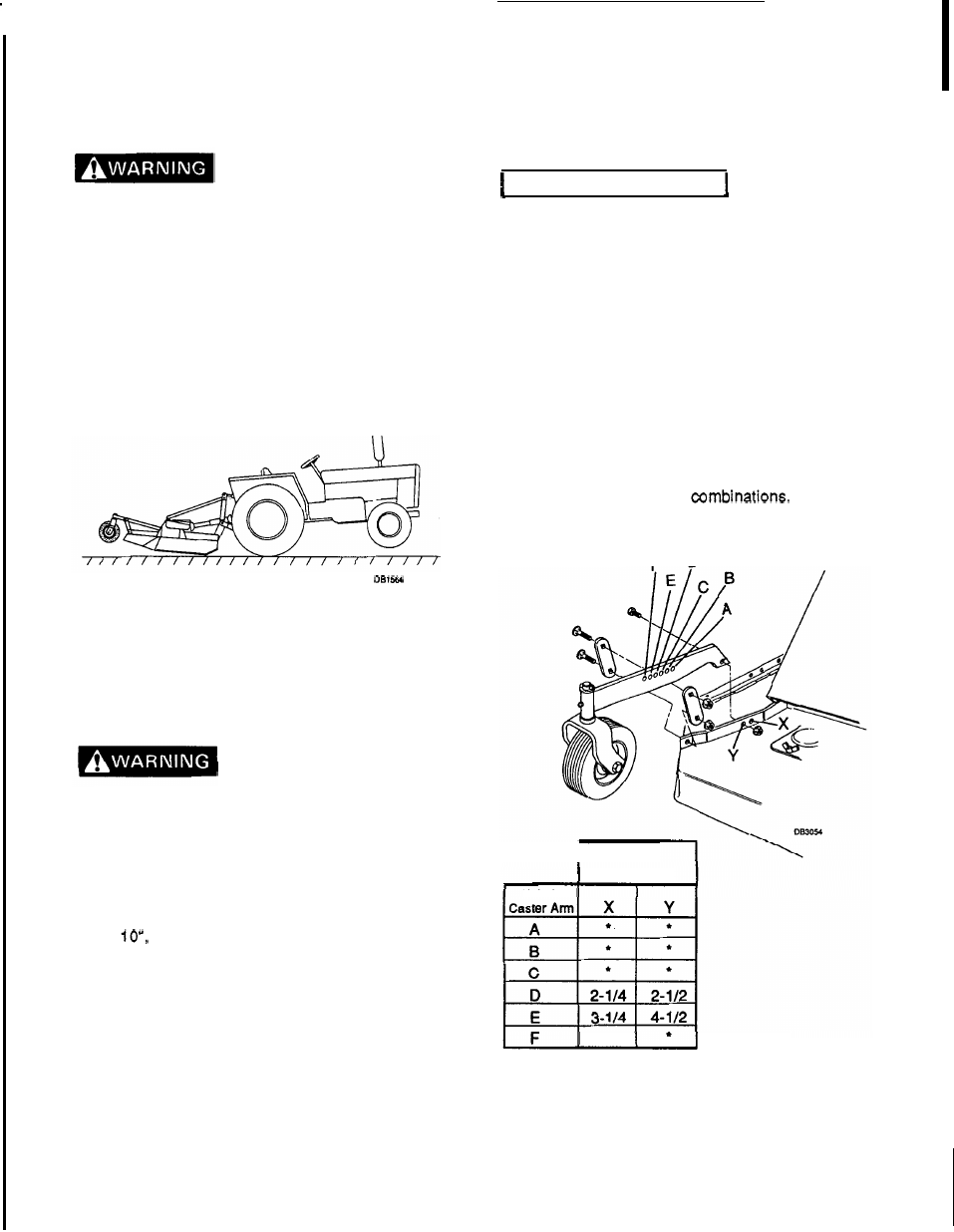
Refer to figure 7. Approximate cutting heights are
provided for various hole
Set caster
arms to your desired cutting height.
E
D
I
Hole in
Frame Rail
Hole in
5-
1
12
*Not
usable
in
these
holes
Figure
7.
Caster Adjustment
14
F-7756
(1
0-89)