Assembly, Installation – HONDA RM752A User Manual
Page 11
ASSEMBLY
Be familiar with all safety practices on pages
4
and
5.
Make certain a l l movement of cutter
components has stopped before openlng
blade
access
cover.
Always wear relatively
and belted
clothing t o
entanglement
moving
parts. Wear sturdy, rough-soled work shoes
and protective equlpment for eyes, hands,
hearlng and head.
Operate PTO
at
2,000
rpm
Turn tractor engine
off,
remove key, lower
mower t o ground before performing any
or
Block mower securely before working under-
neath.
Keep all persons away from operator control
area whlle
adjustments, senrlce
or malntenance.
Make sure tractor PTO sprlng-activated
collar
freely and
Is
seated
In
mower drlvellne spline groove.
Removing Mower From
Box
Remove
components from the comer fillers.
Remove lag screws from crating brackets on both
sides of the mower. Remove mower frame from
DEALER
INSTRUCTIONS
Assembly of this mower is the responsibility of the
dealer. It should be delivered to the owner
completely assembled, lubricated and adjusted for
normal mowing conditions.
Complete check list on page
3
when assembly is
complete.
The mower is shipped partially assembled.
Assembly will be easier
if
components are aligned
and loosely assembled before tightening hardware.
Recommended torque. values for hardware are
located on page
'8.
Select a suitable working area. Lay parts and
hardware out to make location easy. Refer to
illustrations, accompanying text, parts lists and
exploded view drawings.
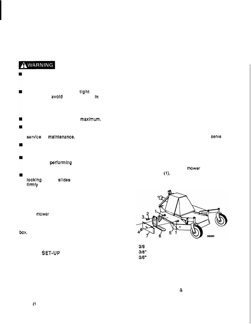
Left Side Skid
and
Shield
Installation
(figure
1)
NOTE:
To make installation easier, put blocks
under the mower frame to raise it off the floor.
The left side shield
(7) and skid
(6)
also
as
guards.
Do not operate mower unless they are in
place and in good condition.
Attach left side shield (7) to mower frame (5) as
shown with
bolts
(1)
and flange locknuts
(4).
Attach left side skid
(6)
to
frame
(5)
as
shown with bolts
lockwashers
(2)
and nuts
(3).
Do
not tighten this hardware as the skid will require
adjustment when cutting height is set.
1.
x
1"
Bolt
2.
Lockwasher
3.
Hex nut
4.
318"
Flanged locknut
5.
Mower frame
6.
Left side skid
7.
Left side shield
Figure
1.
Left Skid Shield Installation
F-7756
0-89)
9