Harbor Freight Tools Central Machinery 10" Disc Sander-Bench Type 47404 User Manual
Page 8
Page 8
SKU 47404
For technical questions, please call 1-800-444-3353.
2.
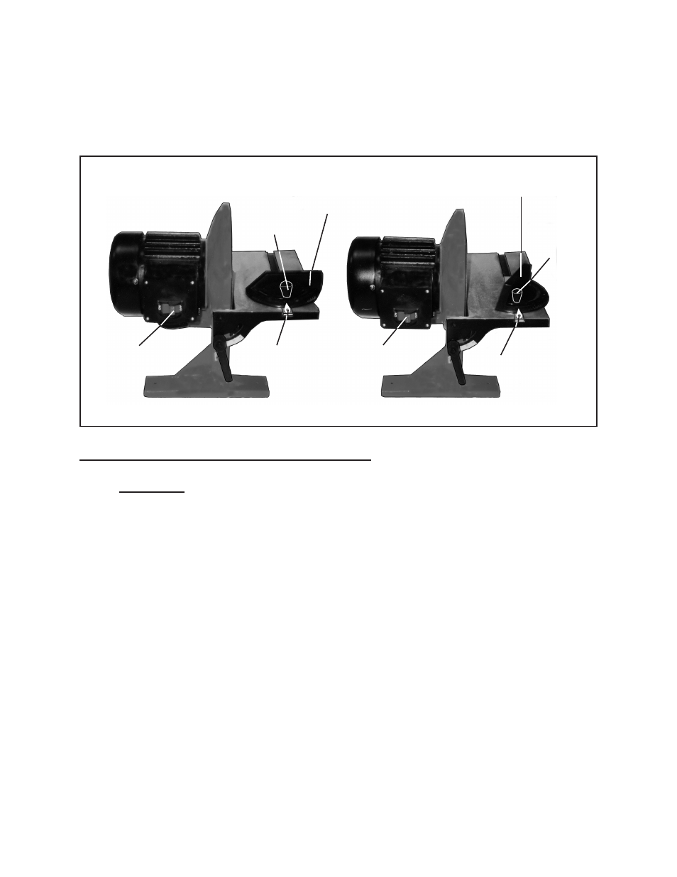
The Miter Gauge (part #3) may be angled from 0 to 60 degrees, right or left. To
do so, slightly loosen the Knob (part #1). Move the Miter Gauge horizontally to
the right or left until the Pointer (part #5) indicates the desired angle. Then, firmly
retighten the Knob Bolt.
(See Figures B, D, and Assy. Diagram.)
MITER GAUGE (#3)
MITER GAUGE (#3)
KNOB (#1)
KNOB
(#1)
POINTER (#5)
POINTER (#5)
SAFETY SWITCH
(#32)
SAFETY SWITCH
(#32)
FIguRE D
FRONT VIEW
To Attach A Sanding Disc To The Disc Sander:
1.
CAuTION: Prior to performing this procedure, make sure the Safety Switch (part
#32) of the Disc Sander is in its “OFF” position and the Power Cord/Plug (part
#34) is unplugged from its electrical outlet.
(See Figures C, D, and Assy. Diagram.)
2.
The Disc Sander requires the use of a 10”, Pressure Sensitive Adhesive,
Sanding Disc (part #14). Additional replacement Sanding Discs are available
from Harbor Freight Tools.
(See Figure B, and Assy. Diagram.)
3.
To attach the Sanding Disc (part #14) to the Disc (part #15) of the Disc Sander,
peel off the protective backing of the Sanding Disc and firmly and evenly stick the
Sanding Disc onto the Disc.
(See Figure B, and Assy. Diagram.)